When generating a solid mesh on a part using Create Solid Mesh (or during the Verifying surface mesh stage of creating the surface mesh on a CAD solid model), the solid mesh engine first checks if the part is watertight. Watertight means that the mesh on all of the surfaces is complete, the lines of the mesh create valid elements, and the mesh properly connects to adjacent surfaces around the perimeter so that the volume is fully enclosed. (If you imagine puncturing the part with a hypodermic needle and trying to fill it with water, the model is watertight if it would not leak. When elements are missing or not properly connected together at edges, then the water would leak, and the mesh is not watertight.) Figure 1 shows an example of a watertight problem.
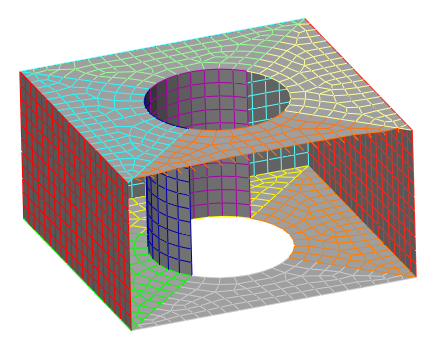
Figure 1: Model with Watertight Problem. Half of the surface of the cylindrical hole is missing from the CAD model. (The outside face of the cube has been hidden to show the inside.)
Follow this procedure for locating the cause of the watertight mesh problems.
- After the part or model has been meshed, a dialog will indicate that some parts failed to solid mesh and/or had watertight problems. After closing the mesh dialogs, the tree view will flag the parts with problems using a yellow exclamation point (!). (Or, use Mesh
 Mesh View Mesh Results to review which parts had problems. The Problems button will summarize the problem parts, and Log File under the Part button will give details about the reason the appropriate part failed.)
 - Use the Draw Design Layer Control command. The elements in the vicinity of the watertight problems are on layers 2 or 6. Hide the other layers (and optionally the other parts that meshed) and zoom in on the problem. By displaying the complete mesh and just the problem layers, it should be possible to understand the cause of the watertight problem. For example, does layer 2 or 6 outline a hole in the mesh? Are the elements severely distorted or twisted?
- Some of the options to fix the problem are as follows:
- For CAD Solid Models. If the problem is a missing surface or holes in the mesh, check the original CAD model for possible problems. In some cases, extremely small or thin surfaces (such as a zero radius fillet) may result in a mesh that does not match between adjacent surfaces. After adjusting the CAD model, try the mesh again.
- For CAD Solid Models. If an entire surface is missing or jumbled, check the tolerances in the FEA Editor environment. Start with the Mesh Mesh Feature Matching command. Check if the problematic part contains any unmatched or multi-matched features. If so, change the Feature matching mesh size and click the Apply button. The goal is to eliminate the unmatched and multi-matched edges by changing the tolerance. (See also Feature Matching.) If the part or surfaces in the problem area are not shaded correctly, use ViewAppearanceCAD Rendering and change the rendering settings. The goal is to get the settings that renders the model accurately.
- For CAD Solid Models. Try a finer surface mesh either in the entire model (Mesh Mesh 3D Mesh Settings), in just the part that failed (right-click part, then CAD Mesh Options Part), or by using refinement points in the problem area (select a vertex or multiple vertices in the problem area, then right-click and choose Add Refinement Points). After changing the mesh size, try to create the mesh again (Mesh Mesh Generate 3D Mesh ).
- For CAD Solid Models and Hand-built Models. If the problem area is small, it may be possible to manually fix the mesh in the FEA Editor environment. Add lines and/or delete lines as necessary to create valid elements. This could be done line-by-line, or by copying or extruding surfaces, and so on. In some cases, the global snap (Draw Modify Global Snap) is beneficial to snap a repair mesh to the existing mesh. Keep in mind that valid surface elements are composed of 3 or 4 sided regions. If adding lines, be sure to use the appropriate part, surface, and layer number for the new lines. After repairing the mesh, right-click the part and choose CAD Mesh OptionsCreate Solid Mesh to create the mesh and check if the problem is fixed.