Drawing planes are used to add geometry to the model. Instead of the freedom of adding the geometry in 3D space, the geometry is always snapped into the plane. In addition to the obvious advantage of being able to draw flat geometry, regions created with construction objects drawn in a plane can be meshed with the 2D mesher. See the page Meshing Overview: Meshing Hand-built Models: 2D Mesh Generation for details.
When using a drawing plane, the FEA Editor environment is in sketch mode. Hence, the terminology sketch and drawing plane will be used interchangeably.
Create a plane
Additional planes can be created by using Draw Draw New Sketch Plane, or by right-clicking on the Planes branch of the tree view and choosing New Plane.
You can select between the three planes parallel to the global axes (XY, YZ or XZ). You can also select the Advanced option or the 3 points option to define an off-axis plane. Activating the Use Offset check box will allow you to offset one of the global planes from the origin. A positive offset places the plane in the positive direction. For example to draw in the X=10 plane, select the YZ option, activate the Use Offset check box and type 10 in the adjacent field.
Enter, use, and exit Sketch Mode
To enter sketch mode to draw on a plane, right-click the desired drawing plane in the tree view and choose Sketch. When in sketch mode, a grid will appear in the display area and the drawing plane is shown in bold in the tree view. All sketching will be done in this plane. The grid can be turned off by right-clicking on the plane in the tree view and clearing Visibility. The spacing of the grid can be customized on the  Options Sketching tab.
Geometry is added to the sketch just like any other geometry: use the commands on Draw and Design panel of the Draw tab. All properties such as part, surface, and layer number, and any object-specific input, are used in the sketch mode just like it is in the 3D mode. (See the page Adding Geometry for details.) The only real difference between adding these objects in 3D mode versus adding them in sketch mode is whether the entered points snap to the drawing plane or not.
When drawing sketch entities, if the cursor is close to a grid point, a lock icon will appear on the cursor. If you click, the item you are drawing will be snapped to that grid point. Likewise, you can snap the new geometry to existing geometry. The points will be projected into the drawing plane.
When an item is added to a sketch, a branch is created under the appropriate part that lists the drawing plane, and this branch includes an entry for each item drawn in that sketch. Click the drawing plane entry under the part to highlight the corresponding items.
To exit sketch mode, right-click the drawing plane and deactivate Sketch. Also, activating the sketch mode for another plane will deactivate the sketch mode for the current plane.
Copy between sketches
Here are the ways to copy items or sketches to other sketches:
- Change Plane. All construction objects assigned to a sketch (the Plane entry in the tree view listed under the part) can be moved or copied to a different plane. Right-click the sketch entry and choose Change Plane. The Transfer to Different Plane dialog will appear and list the available planes in the Target Plane drop-down. (If necessary, create the new target plane beforehand using Draw Draw New Sketch Plane.) If the Copy to target plane option is not activated, the selected sketch will be moved to the target plane. When the two planes are parallel, the move or copy operation is straight forward. When the two planes are not parallel, then the transformation may be harder to visualize (but is still straight forward). The 3D coordinates of each object are converted or projected to local (U,V) coordinates within the existing sketch. The objects are placed in the target plane with the same (U,V) coordinates, then converted to 3D coordinates. So, if a construction line is from (0, 3, 4) to (0, 6, 8) and sketched in the global YZ plane, it would parameterize as a line from (3,4) to (6,8) in (U,V) space. These same (U,V) coordinates in the global XY plane would transform to a line from (3, 4, 0) to (6, 8, 0) in 3D space. Note that the part, surface, and layer number of the construction objects are not changed, so the branch for the new sketch appears in the same part as the original sketch.
- Copy and Paste. Individual construction objects in one sketch of a part can be copied (or cut) and pasted into the same sketch plane in another part. Select the objects (either in the tree view or in the display area), right-click and choose Copy or Cut. Then select the target sketch plane in the tree view, right-click, and choose Paste. Also, you can drag the entries from the sketch in one part to the same sketch plane in another part and drop them into the sketch. Naturally, this operation requires that the target sketch exists in the target part. Other than changing the part number of the copied object, the surface and layer number remains the same.
Pattern Move or Copy command, then the object is no longer associated with a sketch. It becomes a 3D Object and is listed in a separate branch under the part. Convert from 3D objects to a sketch
There are situations in which a construction object is not in a drawing plane, so the tree view lists the item as a 3D object. Some commands are not available on 3D construction objects, such as 2D meshing. These 3D objects can be copied to a sketch as follows:
- Select the 3D construction objects with the Selection Select Construction Objects command.
- Copy or cut the objects to the clipboard. Right-click and choose either Cut or Copy.
- Activate the drawing plane into which the objects should go. (Right-click the appropriate plane under the Planes branch of the tree view and choose Sketch.)
- Paste the 3D objects into the part. Right-click the part name in the tree view and choose Paste. Note that the object must be pasted into a sketch on a different part than the original objects.
Note that the original 3D construction object is not projected into the drawing plane. Therefore, the object should lie in the plane into which it is being pasted.
Calculate the properties of a sketched region
The cross sectional properties of a sketch can be calculated. The guidelines for the sketch or sketches are as follows:
- Draw the region to be calculated using construction objects.
- Draw the objects while in sketch mode.
- The objects can be in different parts but need to be in the same drawing plane. The combination of all parts on all selected sketches will define the region or regions.
- Any drawing plane can be used. The results will be in the local coordinates of the plane.
- The sketch must enclose an area or multiple areas.
- Holes within the area are permitted.
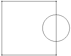
- Regions can overlap, in which case the overlap region is calculated as if it were a hole, but separate regions should not touch. See the following figure.
|
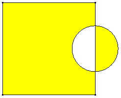
(a) Two overlapping regions (above) are supported by the 2D Moment of Inertia. The overlapping region between the square and the circle becomes a hole in the cross section. The calculations are based on shaded the regions (below).
|
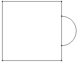
(b) Two regions that do not overlap (above) are not supported by the 2D Moment of Inertia. The problem areas are identified with the inverted triangles (below) when the command is executed. To calculate this area, remove the line in common between the square and the semi-circle. (Alternatively, a duplicate line - one for the square and one for the semi-circle --- could be used. For example, the duplicate would be required if the square and semi-circle were on separate parts and the two regions were going to be meshed with the 2D mesh engine.)
|

Once the sketches are made, either select the plane in the Planes branch of the tree view or select the plane entries in the tree view under the part, then right-click, and choose 2D Moment of Inertia. Selecting the Planes branch is equivalent to selecting each of the individual planes appearing under each part. The calculator will split the combined sketches into a series of horizontal rectangular strips and perform a numerical integration based on these strips. The results are given in the 2D Moment of Inertia Results dialog and consist of the following:
- Area
- Center of Gravity location, given in local coordinate system of the plane (u,v). The global coordinates of the center of gravity can be determined by inquiring on the construction vertex that is added to the model.
- Area moment of inertia about the horizontal and vertical axes of the plane (u and v axes) passing through the center of gravity of the sketch. The orientation of these axes is given as a vector in global coordinates in the Local Orientation
A construction vertex is also added to the model at the location of the center of gravity.
Options Sketching tab. The Save Results dialog will appear when the Save button is clicked. Choose the file name and location of the area calculation results. Activate the Append check box on the Save Results dialog before clicking the Save button to append the current results to an existing file. Otherwise, the existing file will be overwritten with the current results.
Similar calculations can be performed on fully meshed models by using the Analysis Analysis Weight and Center-of-Gravity command. See the page General Options: Weight and Center of Gravity Calculator.