Contact in a nonlinear analysis includes a variety of different types of contact, such as
- impact planes
- surface-to-surface contact between parts
- contact, general contact, coupling element types
- trusses with Curve material model to mimic gap elements
When used in a nonlinear static analysis, keep in mind that all parts of the model must be statically stable at all time steps, all iterations without relying on the contact. The analysis may converge slowly or fail to run if this advice is not followed.
Stabilize the Model
In cases where parts are free to move until they interact with other parts, these free parts must be restrained with weak springs. The goal is to provide stability to all parts, but allow them to move a considerable distance in the process. If contact is not considered on some iteration, the weak springs restrain the part so that the processor can calculate a solution, but then the processor detects that some contact has occurred, and then proceeds with the next iteration and includes contact. Since the weak springs do not exist in reality, the stiffness needs to be set to have minimum affect on the results. The load that is transferred from the model to the ground through the springs should be a small portion of the applied loads. See Figure 1.
In some situations, boundary conditions can be used in a few directions to prevent the parts from moving. For example, a pin inside a clevis may be able to use a boundary condition in the axial direction to provide stability. Weak springs are used in the other directions, the direction the contact occurs, to provide stability while allowing the pin to move into contact.
The details to add the weak spring elements are as follows: (A subassembly is defined here as any number of parts that are bonded together.)
- For a subassembly that is restrained partially or solely by the contact, draw lines (Geometry: Add: Lines) on a new part number. Be sure that the Use as Construction option is not selected and activate the Use Relative option on the line dialog.
- Add a set of three lines, one in each direction X, Y, and Z, connected to nodes on the subassembly. To provide stability in all directions, add a set of lines to three arbitrary nodes that are not in a straight line. (Fewer than three nodes can be used if the subassembly is restrained in some direction by boundary conditions. The goal of the spring elements is to make the part statically stable in all six directions: three translations and three rotations.) The length of the lines has negligible effect on the analysis provided the spring elements do not hinder the motion.
- Select each node on the free end of the spring (Selection: Select: Vertices), right-click, and choose Add: Nodal Boundary Condition. Set the boundary condition to Fixed.
- Right-click the Element Type entry in the tree view and choose Spring.
- Right-click the Element Definition entry in the tree view and choose Edit Element Definition. Enter a value in the Spring stiffness field. Realizing that the spring is connected to the ground, it will transmit part of the applied load to the ground. To minimize the amount of load that is removed from the model, calculate the appropriate stiffness as follows. Estimate the deflection that will occur at the node, and assume some fraction of the applied load will be transmitted through the spring (like 0.1%). The stiffness can be calculated as load/deflection. For example, if the applied load is 1000 lbs and you are willing to let the spring elements take 1 lb (before the parts make contact), and if the estimated deflection of the model at the location of the springs is 0.05 inches, then an acceptable stiffness would be F/d = (1 lb)/(0.05 inch) = 20 lb/in.
- Repeat for other subassemblies in the model as needed.
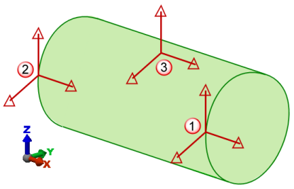
Figure 1: Three Sets of Springs on a Pin Provide Stability
Consider a pin held with contact in a clevis. (The clevis is not shown for clarity.) The springs at 1 and 2 prevent the pin from translating in X, Y and Z, and rotating about Y and Z, but do not prevent the pin from rotating about the X axis (technically, the line joining the nodes at 1 and 2). The springs at 3 prevent the pin from rotating about this. (Technically, the springs in the X and Y direction at point 3 are not necessary but can be included for convenience.)
After the Analysis
If spring elements were used to stabilize any parts of the model, use the Results environment to check the axial force in the springs elements (Results: Element Forces and Moments: Axial Force). The amount of axial force should be insignificant compared to the applied loads in the model.