- With the
 Selection
  Shape Circle and
  Selection Select Surfaces commands still active, draw a circle enclosing the hole at the free end of the crank as shown in the following image.
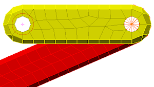
- Click
 Mesh CAD Additions Joint and click the OK button to add the pin joint, which then appears as shown in the following image.
- Select
 View Navigate Enclose (Fit All) (or the equivalent Navigation Bar command). The model displays as shown in the following image.
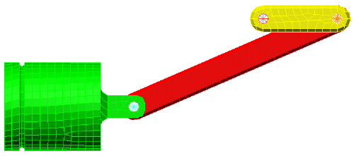
This tutorial is now complete. Use the meshed model to complete the Piston Mechanical Event Simulation tutorial.