- Click
 Analysis
  Analysis Run Simulation.
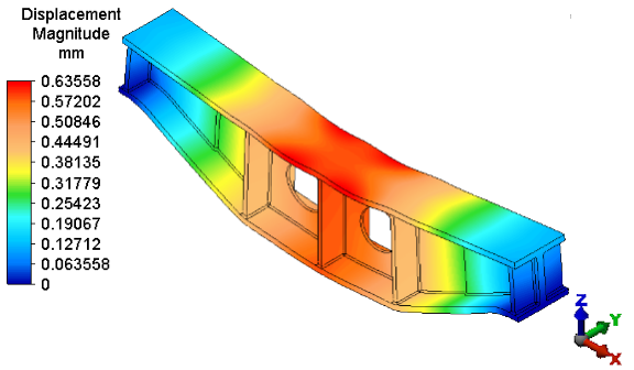
 After solid meshing, the analysis proceeds and the model displays in the Results environment. By default, the displacement magnitude is presented initially. The maximum displacement is approximately 0.64 mm, which exceeds the allowable displacement of 0.5 mm.
- Right-click the 2 <Boundary> heading under Parts in the browser (tree view).
- Click Visibility to hide the 3D spring supports (boundary elements). The model should appear as shown below.
- Click Visibility to hide the 3D spring supports (boundary elements). The model should appear as shown below.