Truss elements are two-node members allowed arbitrary orientation in the XYZ system. The truss transmits axial forces only, and in general, is a three degree-of-freedom (DOF) element (three global translation components at each end of the member).
The three-dimensional (3D) truss element is assumed to have constant area and can be used in linear elastic analysis, materially nonlinear and large displacement geometrically nonlinear analysis. In the large displacement analysis, the Updated Lagrangian formulation is used, but small strains are assumed in the calculation of element stresses.
The 3D truss element can be used as a constraint element to specify the non-zero displacement, uO, on the boundary of the structure by providing the truss element with a very high stiffness, k (10 6 times the largest stiffness in the model), and applying the load k x uO to the structure in the same direction as defined by the truss element.
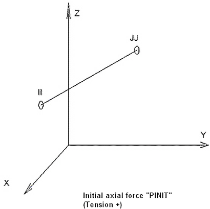
Figure 1: 3D Truss Element
Truss Element Parameters
The first parameter that must be specified for truss elements is the cross-sectional area. This is defined in the Cross-sectional area field in the General tab of the Element Definition dialog. A material model must also be selected in the Material model drop-down box. If the Linear option is selected, a single modulus of elasticity and Poisson's ratio will be used for the entire analysis. If the Curve option is selected, you will need to define the stress-strain curve by entering stress-strain data points.
To include the damping effects, specify a dashpot coefficient in the Dashpot Coefficient field. A dashpot is a linear damping device, such as a shock absorber, which engineers commonly use to damp or smooth excessive motion and vibration. The dashpot coefficient applies a damping force that opposes motion and is proportional to the velocity of one node relative to the other. To include the damping effects in the calculations, you must also activate the Output includes damping effects check box in the Advanced tab.
Use the Analysis Type drop-down to set the type of displacement that is expected. Small Displacement is appropriate for parts that experience no motion and only small strains and will ignore nonlinear geometric effects that result from large deformation. (It also sets the Analysis Formulation on the Advanced tab to Material Nonlinear Only.) Large Displacement is appropriate for parts that experience motion and/or large strains. (The Analysis Formulation on the Advanced tab should also be set as required for the analysis.)

 Options Analysis tab and set the Use large displacement as default for nonlinear analyses option to control whether the Analysis Type defaults to small or large displacement.
 Advanced Truss Element Parameters
Select the formulation method that you want to use for the truss elements in the Analysis Formulation drop-down box in the Advanced tab. If the Material Nonlinear Only option is selected, nonlinear material model effects will be accounted for but all calculations will be performed based on the undeformed geometry. The Total Lagrangian option will refer to the initial undeformed configuration of the model for all static and kinematic variables. The Updated Lagrangian will refer to the last calculated configuration of the model for all static and kinematic variables.
Truss elements can begin the event under a force or strain. You can specify the magnitudes of these loads in the Initial Axial Force and Initial Axial Strain fields in the Advanced tab.
For the stress results for each element to be written to the text log file at each time step during the analysis, activate the Detailed stress output check box. This may result in large amounts of output.
Basic Steps for Use of Truss Elements:
- Be sure that a unit system is defined.
- Be sure that the model is using a nonlinear analysis type.
- Right-click the Element Type heading for the part that you want to be truss elements.
- Select the Truss command.
- Right-click the Element Definition heading.
- Select the Edit Element Definition command.
- In the General tab, select the appropriate material model for this part in the Material Model drop-down box.
- Specify the cross sectional area of the truss element in the Cross-Sectional Area field.
- If the truss elements in this part will have a damping effect, specify this in the Dashpot Coefficient field.
- Press the OK button.