A rigid element connects two nodes of a model, or to transfers a load from a part not in the model, or simulates a boundary that is not modeled.
The rigid element consists of two nodes. Each rigid element part may contain an unlimited amount of elements. However, all the rigid elements in a particular part must share a single node. This common node is treated as the master node during the analysis. See the examples in the following image.
The rigid element is assigned a single stiffness value that is applied against one or multiple degrees of freedom.
|
|
|
|
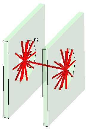
Improper. Rigid elements used to connect two brackets of a larger assembly. The rigid elements (part 2, P2 in figure) are incorrect in this example. Each of the elements within the part do not share a common node. Each rigid element within a part must be connected to one node to create the proper geometry. (Brackets shown with transparency to show the rigid elements more clearly.) |
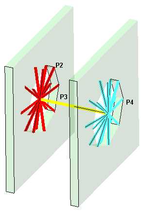
Proper. Each of the rigid elements in each part share one common node. In part 2 (P2), all the rigid elements are connected at one node in the center. Part 4 (P4) is the same way. Part 3 (P3) connects the two sides and can be either one element or two elements (share a node in the center). Part 3 cannot be divided into three elements because they do not share one common node. |
|
Improper and Proper Rigid Elements |
|
When to Use Rigid Elements
- Two parts are connected together by a rigid connection.
- To model the effect of a part that serves as a constraint in the model without modeling the entire part.
Rigid Element Parameters
When using rigid elements, first define the stiffness of the rigid elements in the Stiffness field of the Element Definition dialog box. The deflection or rotation of the element is calculated by dividing the internal force or moment by this value. Units for the stiffness value are not shown, and the value is not converted based on the Display Units. For a true rigid element, the same numerical value can be applied to axial stiffness (force/length) and rotational stiffness (force*length/radian).
Second, specify the degrees-of-freedom against which to apply the stiffness in the Component DOF section by activating the appropriate check boxes. Loads (forces and moments) are transmitted only in the chosen directions, where Tx Ty Tz creates forces in the X, Y, and Z directions. Rx Ry Rz creates moments about the X, Y, and Z directions. The element type to which the rigid element is connected must have the same degree of freedom for the loads to be transmitted.
To Use Rigid Elements
- Be sure that a unit system is defined.
- Be sure that the model is using a structural analysis type.
- Right-click the Element Type heading for the part that you want to be rigid elements.
- Select the Rigid command.
- Right-click the Element Definition heading.
- Select the Edit Element Definition command.
- Specify the spring stiffness of the rigid element in the Stiffness field.
- Activate the check boxes for the degrees of freedom against which this rigid element will be active in the Component DOF section.
- Press the OK button.