A bearing load can only be applied to a cylindrical surface. The surface does not need to be a full 360° cylinder but can be any portion of a cylinder. In addition, the surface can belong to a CAD-based model or a hand-built, structured mesh. A bearing load represents the typical compressive load distribution that occurs in contact areas between shafts and bearings or bushings.
Characteristics of Bearing Loads:
- Bearing loads can consist of a radial load, a thrust load (axial direction), or both.
- Bearing loads are converted to nodal forces. The effect of this conversion can be seen in the Results environment. Forces at edge and corner nodes are noticeably smaller than forces on nearby nodes that are within the interior of the surface. This behavior is normal because edge and corner loads are associated with a smaller element facial area than interior nodes are.
- Thrust loads are distributed along all nodes on the selected cylindrical surface, as shown below.
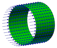
- Radial loads are applied in a parabolic distribution and are always confined to a maximum cylindrical load zone of +/‑90° from the radial vector direction. Consider the images below, which explain how the radial load is distributed in different situations:
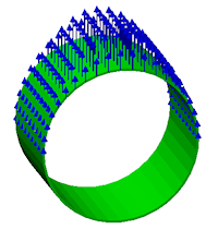
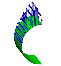
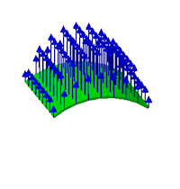
(a) Radial load on a full 360° cylindrical surface. (b) Radial load on a half-cylinder with an edge that is intersected by the radial direction vector. The edges are at 6:00 and 12:00 in this example. (c) Radial load on a <180° cylinder with the radial direction vector passing through the middle of the surface. (180° load zone) (90° load zone) (load applied to the full surface) Important: Regardless of the number of partial surfaces included in a single bearing load, the Magnitude specified in the dialog box is the total load magnitude. This behavior differs from other Autodesk Simulation loads, where the specified magnitude is applied to each selected entity. For example, if a cylinder is divided into four 90° surfaces and a 1,000 pound bearing load is defined with all four surfaces selected, the total load will be 1,000 pounds. Conversely, when a 1,000 pound surface force is applied, the total load is 4,000 pounds (1,000 lbs./surface x 4 surfaces). - The axis orientation of the cylindrical surface is calculated automatically. The thrust vector direction cannot be manually specified, since it is always in the axial direction. However, it can be reversed by clicking the Toggle Vector Direction button.
- The radial load direction can be specified in three different ways:
- Use X, Y, or Z radio buttons to specify a global direction.
- Manually enter custom vector components in the X, Y, and Z fields.
- Click the Radial Vector Selector button and then click two points on the model to indicate the direction graphically.
If the specified vector is skewed relative to the purely radial direction of the surface, it is automatically adjusted to align with the purely radial direction.
- A bearing load may act against an internal surface (such as the inside of a bearing bore), or against an outside surface (such as the shaft extension where a bearing is to be located). The determination of internal versus external loads occurs automatically for solid elements, as shown in the following image:
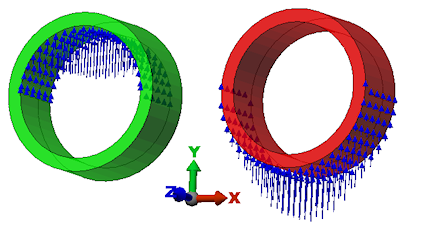
Notice that the vector direction is the same for both parts. The selected surface determines whether the load is internal or external. Both loads are applied in the +Y direction for this example. The left load is applied to the inner surface of the bushing. The right load is applied to the outer surface.
- For planar elements (plates/shells), you must specify whether the load is to be applied to the inside or outside face. The program cannot infer the intended load from the vector alone. When you apply a bearing load to a planar element, the dialog box will contain an additional input field (Load applied to), which is not visible for other element types. Consider the following plate/shell example:
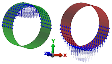
Again, the vector direction is the same for both parts (+Y). The left load occurs when the Inside Face option is selected. The right load occurs when the Outside Face option is selected.
Note: The specification of inside or outside face, in the Bearing Load Object dialog box, is independent of the Element Normal Point, which is used to orient planar elements for other types of loads.
To Apply a Bearing Load:
- If you have surfaces selected, you can right-click in the display area and select the Add pull-out menu. Choose the Surface Bearing Load command. You can also access this command via the ribbon (
 Setup
Setup  Loads Bearing). You can invoke this command from the ribbon either prior to or after selecting the application surface.
 - In the Load Case / Load Curve field, specify the load case number (static analysis) or load curve number (transient stress or nonlinear analysis) that will control the bearing load over time.
- Specify the thrust force and/or radial force in the Magnitude fields.
- Click the Toggle Vector Direction button if you wish to reverse the thrust load direction.
- Choose one of the global X, Y, or Z radio buttons to specify the radial load direction; or...
- Activate the Custom radio button and manually enter the X, Y, and Z vector components in the X, Y, and Z input fields; or...
- Click the Radial Vector Selector button and then click two points on the model to indicate the radial load direction.
Whether manually or graphically specified, the vector is automatically adjusted, if necessary, to conform to the purely radial direction of the selected cylindrical surface.
- For planar element (such as plates or shells), specify whether to apply the load to the Inside Face or Outside Face using the Load applied to menu button.
- Optionally, type a Description of the load in the provided field.
- Click OK to apply the load or Cancel to abort the command.