What are Plate Elements?
Plate elements are three- or four-node elements formulated in three-dimensional space. These elements are used to model heat transfer in thin plate/shell type structures. Plate elements can have convective and radiative loads specified on their surface. Heat fluxes can also be directly specified on their surfaces. Plate elements can also incur heat generation per unit volume.
The highest surface number among the lines that define the element determines the surface number of that element.
Plate Element Parameters
When using plate elements, you must define the thickness of the part in the Thickness field in the General tab of the Element Definition dialog. The element is considered to be drawn at the midplane of the plate element. Therefore, half of the entered value for thickness will be considered on top of the element while the other half will below the midplane. You must enter a value for the thickness to run the analysis. If the plate elements were generated from a midplane mesh in the FEA Editor environment, a thickness will already be defined. The average thickness from each surface of the model will be calculated and used during the analysis. To assign a constant thickness for the entire part, activate the Apply constant thickness check box and type the desired value in the Thickness field.
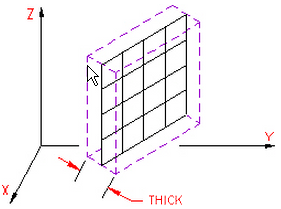
Figure 1: Thickness of a Plate Element
Next you must specify the material model for this part in the Material Model drop-down box. If the material properties in all directions are identical and do not vary with temperature, select the Isotropic option. If the material properties in all directions are identical and vary with temperature, select the Temperature Dependent Isotropic option. If the material properties vary along three orthogonal axes and do not vary with temperature, select the Orthotropic option. If the material properties vary along three orthogonal axes and vary with temperature, select the Temperature Dependent Orthotropic option.
Next, you must specify how the heat flow is calculated in the Heat Flow Calculation drop-down box. If the Projected at Centroid option is selected, the heat flux for this part will be calculated from the derived nodal temperatures using Fourier's law. If the Nonlinear Based on BC option is selected, the heat flux for exterior surfaces with convection or radiation loads on this part will be calculated using the input parameters of the convection or radiation boundary condition and the derived nodal temperatures. The heat flux for interior faces is not affected by this option. If the Linear Based on BC option is selected, the heat flux for exterior surfaces with convection or radiation loads on this part will be calculated using the same method as the Nonlinear Based on BC option except that the heat flux on surfaces with radiation loads will be linearized.
It is only necessary to use the Nonlinear Based on BC or Linear Based on BC options if the actual heat flux output for the radiation or convection boundary condition is desired. The actual heat flows are based on the surface fluxes. For an adequately refined finite element mesh, the heat fluxes at the surface should be equal for all selections.
Next, select the integration order that will be used for the plate elements in this part in the Integration Order drop-down box. For rectangular shaped elements, select the 2nd Order option. For moderately distorted elements, select the 3rd Order option. For extremely distorted elements, select the 4th Order option. The computation time for element stiffness formulation increases as the third power of the integration order. Consequently, the lowest integration order which produces acceptable results should be used to reduce processing time.
Next, specify an element normal point in the Element Normal section. The X Coordinate, Y Coordinate and Z Coordinate fields in this section will be used to define the element normal point for this part of plate elements. The top of a plate element always points away from the element normal point. This is used for determining which side of a plate element is included in an enclosure with body-to-body radiation. See Figure 2.

|
| Figure 2: Determining the Element Normal |
| The edge-on view of the plate element is shown. |
Control Orientation of Plate Elements
If this part of plate elements is using any material model except for isotropic or temperature dependent isotropic, you will need to define the orientation of material axes 1, 2 and 3 in the Orientation tab of the Element Definition dialog. There are two basic methods to accomplish this.
The first method is to select one of the global axes as material axis 1. If you select the Global X-direction option in the Material axis direction specified using drop-down box, the orthogonal material axes follow the X, Y and Z axes as follows:
- Material axis 1: X axis
- Material axis 2: Y axis
- Material axis 3: Z axis
If you select the Global Y-direction option in the Material axis direction specified using drop-down box, the orthogonal material axes follow the X, Y and Z axes as follows:
- Material axis 1: Y axis
- Material axis 2: Z axis
- Material axis 3: X axis
If you select the Global Z-direction option in the Material axis direction specified using drop-down box, the orthogonal material axes follow the X, Y and Z axes as follows:
- Material axis 1: Z axis
- Material axis 2: X axis
- Material axis 3: Y axis
The second method is to select the Spatial Points option in the Material axis direction specified using drop-down box. Next you must define the coordinates for three spatial points in the Spatial point coordinates table. Next, select the appropriate index for the spatial points in the Index of spatial point 1, Index of spatial point 2 and Index of spatial point 3 drop-down boxes. Material axis 1 will be a vector from the spatial point in the Index of spatial point 1 drop-down box to the spatial point in the Index of spatial point 2 drop-down box. Material axis 2 will be perpendicular to local axis 1 and will travel through the spatial point in the Index of spatial point 3 drop-down box. Material axis 3 will be calculated as the cross-product of material axis 1 and material axis 2.
To Use Plate Elements
- Define a units system.
- Be sure that the model is using a thermal analysis type.
- Right-click the Element Type heading for the part that you want to be plate elements.
- Select the Plate command.
- Right-click the Element Definition heading.
- Select the Edit Element Definition command.
- Select the appropriate material model for this part in the Material Model drop-down box.
- If the model was not created with the midplane mesh engine or to specify a thickness for the plate elements, enter this value in the Thickness field. If the model was create with the midplane mesh engine and you want to use the thickness of the CAD solid model, activate the Apply constant thickness check box.
- If you are using body to body radiation where only one side of the plate is involved, define the coordinate to define the side of the plate in the Element Normal section. The coordinate entered in here will define a side of the plate for body to body radiation where only one side is involved. The top of the plate points away from the point.
- If you selected the Orthotropic or Temperature Dependent Orthotropic option in the Material Model drop-down box click the Orientation tab to define the material axes.
- Press the OK button.