Three-dimensional electrostatic tetrahedral elements are 4- or 10-node isoparametric or sub-parametric curvilinear tetrahedra formulated in 3D space. Whether these elements act like conductors (resistive material) or dielectrics (insulators) is determined by the electrostatic analysis type selected (electrostatic field strength and voltage or electrostatic current and voltage). Three-dimensional electrostatic elements are used to model devices such as fuses, transmission lines or porcelain insulators.
Parameters of Tetrahedral Elements
When using tetrahedral elements, in Material Model, specify the material model for this part. If the material properties in all directions are identical, select Isotropic. If the material properties vary along three orthogonal axes or vary with temperature, select Orthotropic. If the material properties will vary with the temperature, select either Temperature-Dependent Isotropic or Temperature-Dependent Orthotropic.
For the tetrahedral elements in this part to have the midside nodes activated, in Midside Nodes, select Included. If you select this option, the brick elements have additional nodes defined at the midpoints of each edge. (For meshes of CAD solid models, the midside nodes follow the original curvature of the CAD surface, depending on the option selected before creating the mesh. For hand-built models and CAD model meshes that are altered, the midside node is located at the midpoint between the corner nodes.) This changes a 4-node tetrahedral element into a 10-node tetrahedral element. An element with midside nodes results in more accurately calculated gradients. Elements with midside nodes increase processing time. If the mesh is sufficiently small, then midside nodes may not provide any significant increase in accuracy.
Orientation of Tetrahedral Elements
If this part of tetrahedral elements is using an orthotropic material model, in the Element Definition dialog box, Orientation tab, define the orientation of material axes 1, 2 and 3.
- The r axis is defined as the vector from Orientation Node 1 to Orientation Node 2.
- The s axis is perpendicular to the r axis; lies in the plane formed by nodes 1, 2, and 3; and is on the same side of the r vector as Orientation Node 3.
- The t axis is the cross product of the r and s axes.
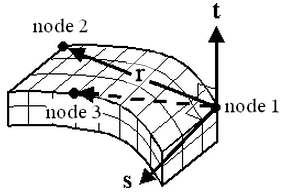
Figure 1: Orientation of the Material Axes
To Use Tetrahedral Elements
- Verify that a units system is defined.
- Verify that the model is using a thermal analysis type.
- Right-click the Element Type heading for the part to be tetrahedral elements.
- Select the Tetrahedron command.
- Right-click Element Definition, and then click Edit Element Definition .
- In Material Model, select the appropriate material model for this part.
- If you selected the Orthotropic or Temperature-Dependent Orthotropic in Material Model, on the Orientation tab specify the nodes to define the material axes.
- Click OK.