The interoperability between Autodesk® Simulation CFD and Autodesk® Simulation Mechanical provides the ability to automatically apply temperature results from a CFD simulation as loads on a structural analysis model. These temperature loads are applied to all nodes throughout the model, and for stress analyses, cause thermal expansion which leads to thermal stress and strain.
The following analysis types support the use of transferred temperature loads:
- Linear_Static Stress with Linear Material Models
- Nonlinear_MES with Nonlinear Material Models
- Nonlinear_Static Stress with Nonlinear Material Models
- Electrostatic_Electrostatic Current and Voltage
- Electrostatic_Electrostatic Field Strength and Voltage
Because the meshing requirements for CFD and structural analyses can be considerably different, interoperability uses the geometric model as the basis for transferring CFD results to the structural model. This provides a great deal of flexibility in that it allows the most appropriate type of mesh to be used for each respective analysis type.
Additionally, interoperability supports 2D planar, 2D axisymmetric, and 3D models, as well as steady state and transient simulations.
Example
An application of this interoperability is to compute the thermal stress in components within an electronic enclosure. Using Simulation CFD, we assign thermal dissipations to several components and simulate the air flow and heat transfer. The result is a temperature distribution on every component in the model.
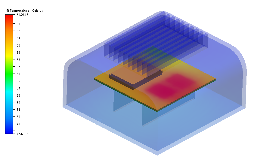
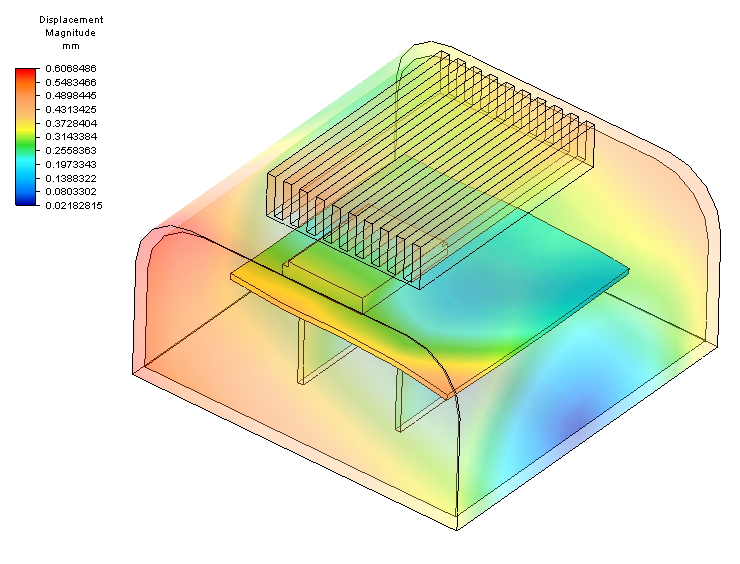
We load the same CAD model into Simulation Mechanical, assign materials and constraints as needed, and select the CFD design study file. When we start the analysis, Simulation Mechanical uses the temperature results as loads, and computes the thermally-induced stress on the components. The result is a view into the system performance that includes the flow and thermal behavior within the enclosure as well as the structural behavior of each component.
Process
- Set up and run the heat transfer simulation in Simulation CFD. The model must contain solid parts in addition to the fluid volume. Note that the fluid volume in the CFD model is not used in the Mechanical analysis; only the solid parts are considered.
- Open the CAD model into Simulation Mechanical.
- Select one of the analysis types listed above.
- Assign materials, constraints, contacts, and loads as necessary.
- For the Linear and Nonlinear analysis types, define the Stress free reference temperature for all parts if the default of 0 is not appropriate:
- From the Browser, right click on the name of the part or parts, and click Edit > Element Definition.
- On the Element Definition dialog, click the Thermal tab.
- Specify the value in the Stress free reference temperature field. Note that the default value of 0 C is not physically realistic for most analyses.
- To use the CFD results:
- From the Setup ribbon, select Parameters.
- For the Linear_Static Stress with Linear Material Models analysis type, enter a multiplier in the Thermal column. For more information about this multiplier, click here.
- For the nonlinear analysis type, be sure to define the Load Curve if it should be different from the default curve. This curve contains the multiplier that is applied to the temperature loads.
- Click the Thermal tab.
- Set the Source of Temperature to be Simulation CFD file.
- Click Browse…, and select the .cfdst file from the cfd study you have run.
- If your design study contains only one scenario, it is listed in the menu below the design study by default. If your study contained several scenarios, select the one you wish to use from the list.
- Select which result step to use from the Which step to use menu.
- From the Setup ribbon, select Parameters.
- Run the analysis, and visualize the results.
Guidelines
There are several guidelines to help you use Simulation CFD to Simulation Mechanical interoperability:
- Be sure to close the Simulation CFD model before you launch the analysis in Simulation Mechanical.
- 2D Modeling:
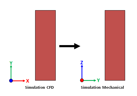
- Simulation CFD solves 2D models in the XY plane. Simulation Mechanical solves 2D models in the YZ plane.
- Before launching the model into Simulation Mechanical, you should re-orient the model in your CAD system from the XY plane to the YZ plane. The model X direction should point in the global Y direction, and the model Y direction should point in the global Z direction.
- Because only the Z axis can be used as the axis of symmetry for axisymmetric models in Simulation Mechanical, ensure that the CFD model uses the Y axis as the axis symmetry. An error is issued if the CFD model is axisymmetric about the X axis. (As with all 2D models, re-orient the model to the YZ plane using the mappings shown above prior to launching into Simulation Mechanical.)
- To reorient a 2D model in Inventor, right click on the sketch in the browser window, and click Redefine. Select the new plane (YZ Plane) from the list of planes below the Origin branch. This automatically re-orients the model according to the direction mapping described above.
- A temperature result cannot be mapped from a temperature initial condition applied in the Simulation CFD model. To transfer an initial temperature:
- On the Simulation CFD solve dialog, set the number of time steps to 0, and click Solve. This saves the temperature field defined by the initial condition to a results set (*.t0).
- Continue the simulation from the saved result set to compute the time history of the temperature distribution.
- The units system in the Simulation CFD and Simulation Mechanical analyses do not have to be the same. However, because Simulation CFD does not support the micron length units, you should not use microns in the Simulation Mechanical analysis.
- Because Simulation CFD and Simulation Mechanical treat multi-body parts from CAD differently, it is best not to create parts that have multiple disconnected volumes. Ensure that all parts are continuous bodies. If a part does contain disjoint regions, the number of parts in the Simulation Mechanical model may be different from that of the Simulation CFD model. This may prevent results from being correctly applied to certain parts in the Simulation Mechanical model.
- It is acceptable to use the geometry tools in Simulation CFD to create an internal volume or an external void for the CFD simulation. Note, however, that any parts created in the Simulation CFD model that did not exist in the CAD model will not come into the Simulation Mechanical model. For this reason, you should only assign fluid materials to such parts, and not use them as solids.