Surface Mesh Enhancement Options: Mesh Shape/Quality tab
Meshing Retries
This section allows you to control the parameters involving the retry operation that occurs when a mesh cannot be enhanced with the current parameters.
Retry Number: The value in this field is the number of times that the enhancer will retry the enhancement.
Retry Fraction: The value in this field will multiply the mesh size to calculate the new (smaller) mesh size that will be used on the next retry.
Mesh Type
The Mesh Type pull-down has options to generate a quadrilateral or triangular mesh.
Feature Controls
The surface mesh enhancer will take the existing mesh and put a new surface mesh on the model. The way the mesher finds the outline of the model is by using feature lines. Feature lines define the boundaries of the volume that the model encompasses. The position of feature lines will stay in the model when a new mesh is created but can be divided into smaller lines or made into larger lines. In other words, a feature line is a key edge of the model. A feature cannot change positions without changing the outline of the part. But the size of the elements along the feature can bet bigger or smaller.
There are two different ways to define feature lines in your model, the Feature Layer and the Feature Angle fields.
Feature Layer: You can specify lines in the mesh that you want the surface mesh enhancer to maintain. To specify a feature line, select the lines (Selection Select Lines) change the layer number to a specific layer number (Draw Modify Attributes). Then, set the Feature Layer to that same number. When you run the surface mesh enhancer, the feature will be maintained and the mesher will not mesh across this feature.
Feature Angle: The feature angle (expressed in degrees) is a setting used to determine whether a line is or is not made into a feature line. Feature lines are generated from the intersection of two elements. The elements' normal directions are calculated, and their difference is called the out-of-plane angle. If the two elements generate an out-of-plane angle larger than the feature angle, the line created by the intersection of the two elements is made a feature line. If the out-of-plane angle generated by the two elements is smaller than the feature angle, the line generated by their intersection is not treated as a feature line.
In other words, if the angle between the planes of two adjacent elements is larger than the feature angle, then the common edge between the two elements becomes a feature line segment. The mesher will not mesh across feature line segments.
A small feature angle will result in more feature lines, a more detailed mesh and a larger model that will take longer to analyze. A larger feature angle will eliminate excess feature lines, help reduce the noise or erroneous lines that can accompany some imported models, and produce a smaller model that can be analyzed in less time.
Too many feature lines (angle is too small) can prevent the mesher from finding a suitable mesh. Too few feature lines (angle is too large) can round off large, sharp edges as they are meshed when they should be kept as features. A large feature angle can also cause gaps to appear along the features. If these gaps are small, they can reduce the mesh size necessary for the mesher to mesh the model. The mesher assumes that the feature angle will be smaller than 90 degrees so that it can trace curves along the surface.
Delete Feature Layer: This option is used to prevent edges from becoming features even if they normally would be considered features based on the feature angle. It can be used to improve the quality of the mesh. You can remove skewed feature lines that would force the mesher to create triangular and/or skewed elements. It is not designed to remove features defined by feature angles larger than 89 degrees. Consequently, it cannot be used to remove small holes from a model. Removal of unwanted features, like small holes, should be done in a CAD package before generating the surface mesh.
The default layer number for this option is layer number 10.
Open Plate Model: This option lets you specify whether or not the surface mesh is watertight. Checking this box means that the mesh is not watertight; that is, you are enhancing the mesh for a plate model.
Features Only: The surface mesh enhancer will not perform the mesh generation if you use this option. This option causes the surface mesher to generate a separate model named feature.fem. The lines in the feature.fem file represent the feature lines in the model (based on the feature angle).
The features only file can be used to check whether the feature angle has been specified correctly. Since the surface mesher does not mesh across feature lines, all the lines in feature.fem file would be in the final model if it were enhanced with the same settings.
Examples
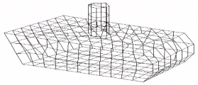
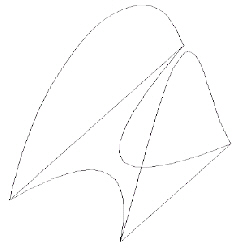
This section shows two models. The free-form model, shape, will be used to show what happens when the feature angle is too small. The more geometric model, tank, will be used to show what happens when the feature angle is too large. Both of these models can be meshed reasonably well using the default settings for feature angle and curve angle. Figures 1 and 2 show the meshes created with the default settings. The feature lines created in the feature.fem are acceptable. Figures 3 and 4 show the feature lines for the models.
|
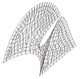
Figure 1 The Shape Mesh with Default Settings |
|
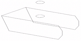
Figure 2 The Tank Mesh with Default Settings |
|
Figure 3 Feature Lines for the Shape Model |
|
Figure 4 Feature Lines for the Tank Model |
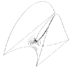
If the feature angle is too small, then too many feature lines are generated. Some clusters of feature lines may seem to end in space and be difficult to mesh. You may need to decrease the mesh size until it is small enough to mesh the clusters. Figure 5 shows the result of setting the feature angle to 10 degrees. To remove the clusters, the mesh size is about 1/3 the default mesh size and about 10 times as many elements must be generated.
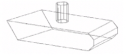
If the feature angle is too large, then feature lines will be missing and those features will be rounded off in the meshed model. Figure 6 shows the result of setting the feature angle to 70 degrees. Notice that the features defining the front edge are missing. Figure 7 shows the meshed version where the edges representing these features fluctuate based on element shape. To emphasize the effects of the feature angle and the curve angle, the mesh size for the tank model is set slightly larger than the mesh size for the default case.
|
Figure 5 The Shape Model with a Feature Angle of 10 Degrees |
|
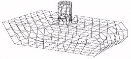
Figure 6 The Tank Model with a Feature Angle of 70 Degrees |
|
Figure 7 The Tank Mesh with a Feature Angle of 70 Degrees |