An end release can be applied to a beam element.
An end release allows either or both ends of a beam element to rotate about or translate along one or more of the local axes of the beam.
Apply End Releases
If you select one or more beam elements using the Selection  Select Lines command and right-click in the display area, you can select the Add pull-out menu and select the Beam End Releases command to add an end release to each beam element. You can also access this command via the ribbon (Setup Beam Loads Beam End Release).
Activate the check boxes in the I Node and J Node sections to release the rotation (R) or translation (T) of that node in one of the local directions. For example, T1 refers to the translation along the local 1 axis, and R1 refers to the rotation about the local 1 axis. You can use the buttons to the right to set the releases to certain values.
Visibility Object Visibility Element Axis commands. Axis 1 points in the direction from the I Node to the J Node. If axis 1 needs to be reversed for some elements, this can be done by selecting the elements (Selection Select Lines), right-clicking, and choosing Invert I and J Nodes. In a normal beam member, the displacement and rotation result is continuous from one element to the next. Since end releases free a translation or rotation at a node, there is a theoretical step-change in that result at the node. For example, a rotational end release creates a hinge. The rotation angle at the end of one beam does not equal the rotation angle at the start of the next beam. (See figure (a) and (b) below.) However, the FEA results give just one value of displacement and rotation at a node. Therefore, the effect of the end release is not visible at the node. (See figure (c) below.) If necessary, add an extra node close to the end release to see the effect more clearly.
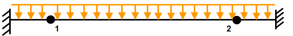
(a) Fixed-fixed beam with a hinge point at 1 and 2.
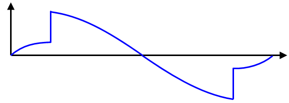
(b) The theoretical rotation or slope of the beams. Note how the result is discontinuous at the hinge points.
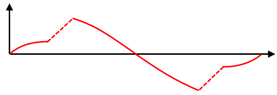
(c) Since there is only one rotation result in the analysis at the hinge points 1 and 2, the rotation results are presented as continuous. The length of the step (shown by dashed lines in the figure) is determined by the size of the element with the end release.
Since the internal shear forces and moments are calculated at each node on each element, discontinuities can be displayed in these results.