A beam preload creates an axial load over the length of a beam element. This is useful for simulating fasteners, wire rope, and other loads that are internal to the model or part (as opposed to an external load such as a nodal force). Unlike external loads which are constant throughout the analysis, the preload magnitude is the magnitude in the element if the rest of the structure were infinitely stiff. Since the structure is not infinitely stiff, one result of a preload is that the structure deforms and relieves a portion of the preload. See Practical Considerations below.
Apply Preload Loads
In linear analyses, beam preloads are available only for static stress. They are not available for Natural Frequency (Modal) with Load Stiffening nor Critical Buckling Load.
In nonlinear analyses, beam preloads are available for MES and for Static Stress with Nonlinear Material Models. It is also possible to apply a beam preload in a Natural Frequency (Modal) with Nonlinear Material Models analysis. However, it will produce no effect on the results, since this analysis type does not account for load stiffening effects. Beam preloads are not available for an MES Riks analysis.
- Define the Element Type for the part to be Beam elements.
- Select one or more beam elements using the Selection
 SelectLines command.
 - Right-click in the display area and choose the Add pull-out menu and select the Beam Preload command to add a preload load each beam element.
- Enter the magnitude of the preload in the Axial Force field. A positive value indicates the element is initially in tension, so the analysis draws the beam ends together. A negative value indicates the element is initially in compression, so the analysis moves the beam ends apart.
- A beam element with a preload has the symbol B on the line segment. To modify the preload, either select the preload entry in the FEA Object Groups branch of the tree view, or select the B symbol in the display area while in the line selection mode (SelectionSelectLines).
- In addition to the context menu command, you can also click the Beam Preload command within the Beam Loads panel of the ribbon Setup tab.
- The initial strain is considered to be zero. Thus, the calculated strain does not appear to agree with the calculated stress unless you consider the prestrain.
- For linear analyses, the preload is applied to all load cases in the analysis. It is not affected by any load multipliers.
- For plastic material models in a nonlinear analysis, the pre-strain is calculated, so the effect appears in the strain results.
Practical Considerations
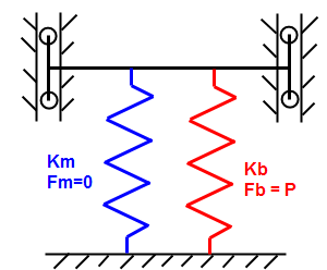
As noted above, some of the preload applied to the beam element is relieved in the analysis because the members compress in response to the load. If the preload provided is intended to be the final load, such as the preload in a bolt due torquing it with a torque wrench, then the beam preload applied must be increased to compensate for the compression of the parts. If the stiffness of the members and the final load were known, the initial preload to apply to the beam elements could be calculated as follows:
|
Consider a beam (represented by red spring K b ) that is stretch to create a preload of amount P, and then attached to the members (represented by blue spring K m ). The beam and member then compress an amount Δ. Since the beam is stretched before attaching to and compressing the member, the final load F' in the beam equals the preload minus the stiffness times the compression, while the equal (but opposite) load in the member equals the stiffness times the compression. Thus, there are two equations and two unknowns (F' and Δ). |
|
Final load in beam F' = P - K b Δ |
|
Final load in member F' = K m Δ |
Solving these two equations for the final load F' gives
F' = P[K m /(K m +K b )]
where K b is the stiffness of the beam, K m is the stiffness of the member, and P is the preload applied to the beam.
For a bolted connection, there are many formulas for calculating the stiffness of the members depending on the assumptions about the pressure distribution under the bolt. One such formula is as follows which considers an apex angle of 30 degrees for the pressure distribution and a washer diameter of 1.5 times the bolt diameter:
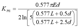
where L is the total thickness of the bolted members and d is the diameter of the bolt and hole. (Reference: Budynas, Richard G and Nisbett, J. Keith, Shigley's Mechanical Engineering Design, McGraw-Hill, Inc, Eighth Edition)
The item of interest for this topic is the ratio P/F'. In many cases, the known preload is the final load in the bolt and member (F'), so the above formulas can be used to calculate the preload P to apply to the beam elements. The following table gives several results. For example, when L/d is 2, the preload to apply to the beam elements is 1.35 times the final preload in the bolt and members. (Obviously, each design is different, so the above equation for K m and the table are only representative of the approach.)
|
Length/Bolt Diameter L/d |
Preload/Final Load P/F' |
| 0.50 | 1.60 |
| 1.00 | 1.48 |
| 2.00 | 1.35 |
| 3.00 | 1.28 |
| 4.00 | 1.23 |
| 6.00 | 1.17 |
| 10.0 | 1.12 |
Notes:
- If the members are composed of several materials, the stiffness can be calculated as springs in series. Recall that the equivalent stiffness K eqv in this situation is found from
1/K eqv = 1/K 1 + 1/K 2 + 1/K 3 + .
- If one material is much weaker than the others, such as a soft gasket material, then the softer material governs and K eqv ≈ K gasket .
- In some critical cases, it may be necessary to perform the analysis with no loads applied to the model except for the preload to determine what preload P is required to get the final load F'.
Similar approaches can be used when using temperature to apply a preload to part of the model.