Next, we will apply nodal forces to the nodes around the edge of the hole in the horizontal part.
- Click inside the hole in the horizontal part, near its edge, to select the surface.
- Right-click and choose Select Subentities
 Vertices. All the nodes belonging to the previously selected surface will now be selected, as shown below.
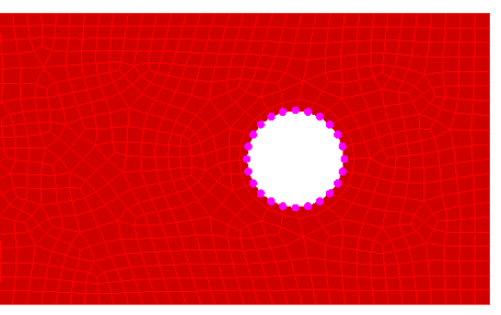
- Click
 Setup Loads Force. Notice that the title bar of the dialog indicates the number of selected nodes.
 - Type -2500/24= in the Magnitude field. This field will now show the total force divided by the number of selected nodes (-104.167), which is necessary because the specified magnitude is the load applied to each individual node. The force is negative because we want it applied in the -Z (downward) direction.
- Select the Z radio button.
- Click OK.
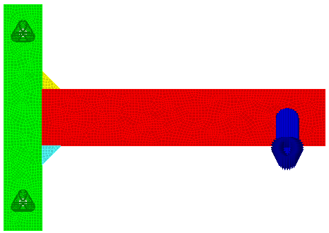
The model displays as shown in following image.