To mesh a 2-D model, each part must contain a single enclosed area. The weldment model requires four parts. We will start by creating the vertical part. For the nodes to match at the interface of two parts, the wireframe geometry has to match. Therefore, we must divide the right side of the vertical part so that it has line segments matching the three adjacent parts. We will do this in a later step.
- Right-click the Plane 2 < YZ(+X) > heading under the Planes heading in the browser (tree view). Select Sketch. To use 2-D elements in an analysis, the model must be constructed in the YZ plane.
- Click
 Draw
Draw  Draw Rectangle.
 - Press Enter to specify the origin as the first corner.
- To specify the point (0, 2, 12) as the opposite corner, type 2 in the Y: field, type 12 in the Z: field, and press Enter.
- Click Apply.
- Press Esc to exit the command.
- Click
 Draw Draw Circle Center and Radius.
 - To specify the point (0, 1, 1.5) as the center of the circle, type 1 in the Y: field, type 1.5 in the Z: field, and press Enter
- To specify the point (0, 1, 1.75) as a point on the circle, type 1 in the Y: field, type 1.75 in the Z: field, and press Enter.
- Click Apply.
- Press Esc to exit the command.
- With the
 Selection Shape Point or Rectangle and
  Selection Select Construction Objects commands active, click the circle.
 - Click
 Draw Pattern Move or Copy.
 - Activate the Copy check box and type 9 in the Total distance field.
- Select DZ and click OK.
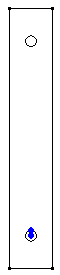
- Select
 View Navigate Enclose (Fit All).
 - Right-click the Planes heading and clear Visibility of All. The model should now look like the image below.