Next, we will apply the nodal forces to the top corner nodes.
- With the
 Selection
  Shape Point or Rectangle and
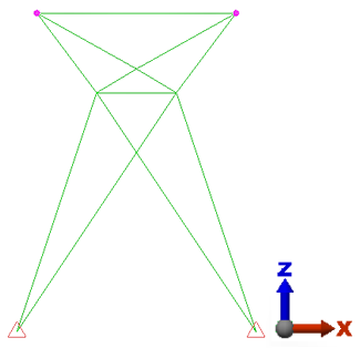
  Selection Select Vertices commands active, click the upper-left node of the model.
 - Hold down the Ctrl key and click the upper-right node. Two vertices should now be selected, as shown below.
- Click
 Setup Loads Force.
 - Type -5000 in the Magnitude field.
- Select the Z radio button. Each node receives the specified force magnitude, so we have applied a total force of 10,000 lbf in the -Z direction.
- Click OK.