- Select one or more objects.
- To open the Motion quick edit dialog, click Edit on the Motion context panel.
- Select Nutating as the Type.
- If the flow drives the motion, check Flow Driven.
- Click Edit... on the Edit Motion line. This opens either the User Prescribed or for Flow-Driven Motion Editor.
- Specify the Nutating Motion Parameters: Tilt Axis, Axis of Nutation, Center of Nutation, Initial Position, Minimum And Maximum bounds (for flow-driven only).
- Click Apply.
Tilt Axis
The tilt axis is the axis normal to the disk. As the disk nutates, this is the axis that is pinned at the Center of Nutation and rotates about the Axis of Nutation.
- Key in the vector representing the Tilt Axis, or open the pop-out dialog.
- Select the Global X, Y, or Z axis to define a Cartesian direction.
- To graphically set the direction, click the Select Surface button, and select a surface. The axis will be normal to the selected surface.
The Tilt Axis on an actual nutating device is shown:
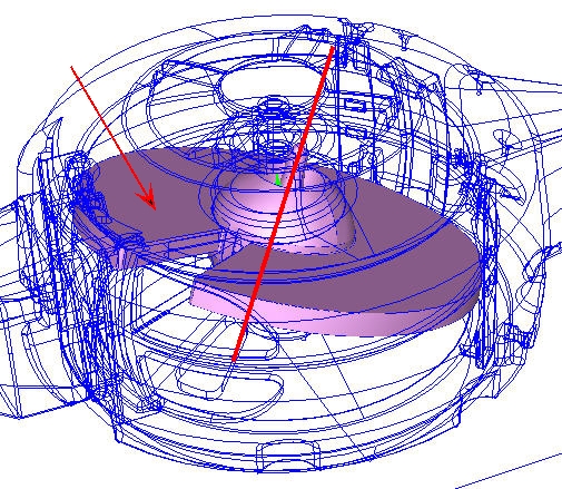
Using the Pick Option, select the surface indicated in the graphic as the surface normal to the Tilt Axis. The resultant Tilt Axis is shown on the disk.
The absolute orientation of the tilt axis will change as the object nutates, but the orientation relative to the object will remain constant. The direction of this axis determines the direction of Nutation according the right hand rule convention.
Axis of Nutation
The Axis of Nutation is the axis that remains constant throughout the nutation process.
- Key in the vector representing the Axis of Nutation, or open the pop-out dialog.
- Choose the Global X, Y, or Z axes to choose a Cartesian direction.
- To graphically set the direction, click the Select Surface button, and select a surface. The axis will be normal to the selected surface.
Because this axis does not move, it is often convenient to construct the model such that a Cartesian axis is the Axis of Nutation. This allows easy specification of the axis. The Axis of Nutation is shown:
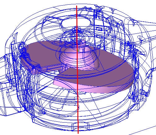
In this case, the Axis of Nutation is the Global Y axis.
Center of Nutation
The Center of Nutation is the center point of the nutating object.
There are two ways to specify this:
- Key in the coordinates or open the pop-out dialog, or
- Click the Select Surface button. After selecting a surface, the centroid of the selected surface will be the Center of Nutation.
The center point is the center of motion, and is typically the center of the object. Because of this, it is often convenient to construct the CAD model such that the center of the nutating object is at a known coordinate. In the example shown below, the Center of Nutation is actually the origin (0,0,0), which made defining it very easy:
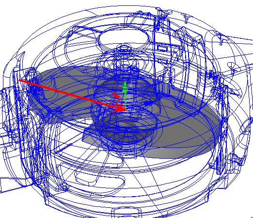
The Center of Nutation in this model is at the origin.
Initial Position
This slider on the pop-out dialog is used to modify the initial angular position of the object from the as-built location in the CAD model. This is very useful for fine-tuning the model in case the initial position of the object in the model is not quite correct.
The positive direction of adjustment is in the direction defined by the Axis of Nutating. Use the slider to rotate the object about the axis of nutation in both the positive and negative directions.
Minimum and Maximum Bounds
Use the Minimum and Maximum fields to set the bounds of rotation for flow-driven nutating motion. (This is only required, and available, for flow-driven nutating.) Bounds can be set by keying in an angular bounding position or using the slider on the pop-out dialog to select an angular position. The default state is that the motion is unbounded.
The minimum and maximum boundaries can be specified differently, if necessary. Note that the bounds are relative to the initial position specified with the Initial Position Slider.