Il tipico modello CAD è costituito da parti solide, ma non da parti fluide. La regione fluida viene in genere contenuta all'interno e attorno ai solidi, ma nella maggior parte dei casi non è esplicitamente creata come parte del modello geometrico.
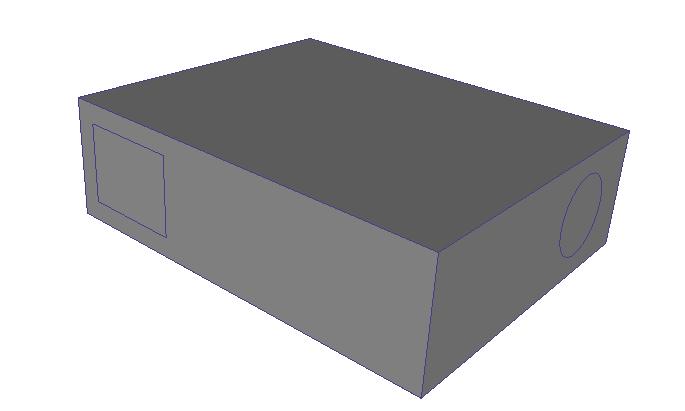
Una geometria costituita solo da parti solide in genere disporrà di aperture in cui il fluido di lavoro (aria, acqua, ecc.) entra ed esce:
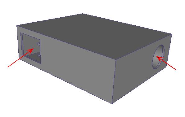
In questo stato, un modello di questo tipo non è adatto a un'analisi del flusso (a causa della mancanza di una parte di flusso).
Lo strumento Riempimento area vuota fornisce una struttura per creare superfici di chiusura che circondano un vuoto interno a tenuta stagna. Le superfici e il volume e che vengono creati sono geometria effettiva che può avere condizioni al contorno, materiali, e così via, e hanno delle mesh assegnate come parte del modello di simulazione.
To access Void Filling, click Setup > Setup Tasks > Geometry Tools, and click the Void Fill tab.
Alternatively, right click on the Geometry branch of the Design Study bar, and click Edit...
Void Fill is a two step process:
Step 1: Create the Capping Surfaces
Capping surfaces must be planar, and cannot overlap any other surfaces.
For each opening, select the edges that bound the opening. Only edges that contact the first selected edge of an opening and are co-planar with it can be selected.
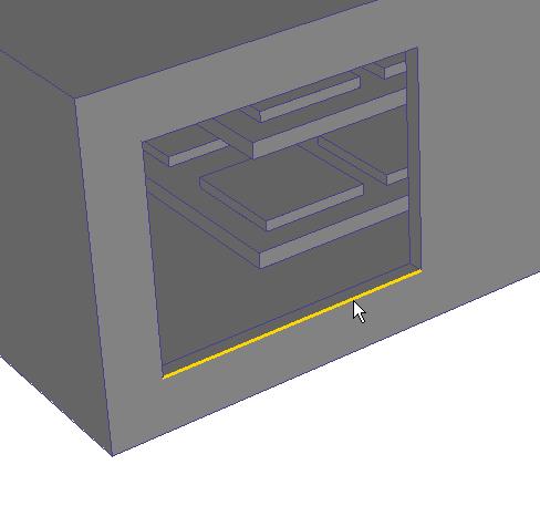
Auto-close attempts to automatically identify the remaining edges needed to close the surface loop.
In the image above, there are two possible paths that will create a planar surface. Because the loop is ambiguous, Auto-close cannot automatically close it...
After selecting the next edge, the entire loop is no longer ambiguous, and can be automatically completed:
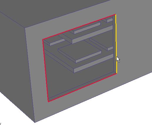
Build Surface becomes active when a loop is completely defined. Click it to build the surface.
Repeat the process for the remaining openings.
Step 2: Complete the Internal Volume
When all bounding surfaces are complete, click the Fill Void button.
If the void fill region is constructed, the following message is written to the Output bar:
“Fill Void Successful; there were 1 part(s) created.” (The actual number of created parts will be written in the message.)
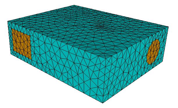
Regions created with the Void Fill tool are added to the Parts branch, and are named Volume. They are part of the simulation model, and can be meshed.