After a head is defined, either on the end of the main cylinder or on a nozzle, then multiple nozzles can be added to the head. Activate the check box Include nozzles on head and click the Nozzles on head button. This will display the Nozzles on Head dialog.
The Nozzle on head drop-down will show the input for the selected nozzle. Click the Add nozzle button to add another nozzle to the head. Click the Remove nozzle button to delete the currently selected nozzle. The Duplicate nozzle button will copy the existing nozzle in case the vessel has similar nozzles; simply change the parameters that make the duplicate nozzle unique.
The input for nozzles on heads is mostly self explanatory with the following clarifications:
Geometry tab
- When creating a solid mesh, the diameters are to the outside of the nozzle. The thickness extends inward.
- Orifice with no nozzle will create a hole in the side of the head using the nozzle diameter.
- Taper angle of nozzle: Since the input diameter for the nozzle is at the end away from the intersection with the head, a positive taper angle means that the nozzle is larger at the intersection than the opposite end. Using the nomenclature in Figure 1, Tan(α) = (De - D)/2/L where D is the user-specified diameter and De is the diameter of the nozzle at the head.
- Use the Include nozzle on head check box to activate or deactivate the nozzle. Deactivating the nozzle will hide it but retain the input.
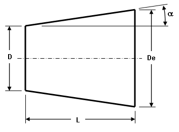
Key:
D = diameter of nozzle (user input)
De = diameter at intersection of head
L = length of nozzle (user input)
α = taper angle (user input). Tan(α) = (De - D)/2/L
Figure 1: Tapered Nozzle
Position tab
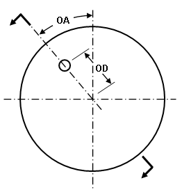
See Figure 2 for a definition of the values that position the nozzle.
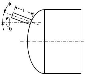
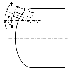
- The Intersection is based on drop-down determines whether the dimensions are based on the Actual head or the theoretical Flat head; that is, the end of the cylinder. For example, if a nozzle on the end of a cylinder is parallel to the axis of the cylinder (Phi angle=0), and if the nozzle length is 5 feet, then the end of the nozzle will be 5 feet from the cylinder when using Intersection is based on: Flat head regardless of the offset distance. When using Intersection is based on: Actual head, the distance from the end of the nozzle to the cylinder depends on the dimensions of the head, the offset distance, and so on.
- When activated, Normal to the head calculates the Phi angle and Theta angle so that the nozzle is perpendicular to the head.
|
End View of Head Nozzle not shown for clarity |
Cross Section View Nozzle intersection based on actual head.
Cross Section View Nozzle intersection based on flat head. Only the portion of the nozzle beyond the actual head is created. |
|
Key: OA = Offset angle OD = Offset distance L = length of nozzle φ = Phi angle ϑ = Theta angle. |
|
|
Figure 2: Positioning a Nozzle on a Head |
|
Thickness tab
If you are creating a brick model, the thickness of each part or the nozzle can be specified in the Thickness tab. (For plate/shell meshes, the thickness of each region is specified in the FEA Editor under the Element Definition.)