Once all of the sketches are complete, you can generate the 2D mesh by selecting the drawing plane under each part headings in the tree view, right-clicking, then choosing the Create 2D Mesh command. The 2D Mesh Generation screen displays.
All parts on a given plane should be meshed together to assure that the meshes match between the parts when required. Different planes are meshed separately.
2D mesh generation matches the mesh between different parts only if the parts are meshed simultaneously. Parts meshed separately in different planes normally do not have the meshes matched.
When you select a plane heading in the tree view and select the Generate 2D Mesh command, the 2D Mesh Generation dialog will appear. The dialog includes the following features.
Element Shape
- Quadrilateral: Selecting this option instructs the mesher to mesh the region using only quadrilateral elements. Note that this option always splits each segment into a minimum of two divisions. When very short segments exist, some distorted elements may occur in the area. Using a mixed mesh or adding refinement points (Specifying Edge Divisions and Refinement Points) may be helpful.
- Triangular: Selecting this option instructs the mesher to mesh the region using triangular elements.
- Mixed: Selecting this option instructs the mesher to mesh the region using both quadrilaterals and triangles. This option may be useful when the wireframe contains very short segments or thin parts. The mixed mesh does not require each segment to be split into a minimum of two elements, and this results in a more uniform mesh around these short segments
Surface Number
The option Use Surface Number of Construction Object controls the surface number of the lines generated in the mesh.
- When not activated (unchecked), the surface of each edge of the mesh is placed on a unique number. (Technically, the surface number of each edge is equal to the construction object's number - as shown in the tree view --- plus 1. Thus, no two parts will have the same surface number around the perimeter.)
- When activated (checked), the surface number of each edge of the mesh is placed on the same surface number as the construction object's surface number. This is convenient when multiple edges are destined for the same load. For example, imagine a tube sheet in a heat exchanger with 50 holes. To apply a boundary condition around the perimeter of these 50 holes (to simulate the connection to the tubes), draw each hole in the sketch on the same surface number. After meshing, select this one surface to apply the boundary condition.
In both cases, the surface number of the interior lines is 1. Thus, do not use surface number 1 for a construction object that needs a surface-based load or boundary condition when the Use Surface Number of Construction Object option is used.

 Options Sketching Color of construction objects follows View: Color By. The color is either black or follows the part, surface, layer number of the object which is set by the View Appearance Color By drop-down menu.
 The surface number of the construction object can be set while the object is drawn. After it is drawn, it can be changed by selecting the object (Selection Select Construction Objects), right-clicking, and choosing Edit or Edit Attributes.
Global Element Size
- Mesh Density This option is roughly the number of elements in a rectangle completely enclosing the geometry. Holes, arcs and refinement points will affect the actual number of elements generated. If this item is active then the non-refined mesh size is set based on the number of elements that will fit in a rectangle which encloses the model. The actual number of created elements can be larger or smaller than the specified density. If the model does not fill the entire enclosing rectangle, the number of created elements can be much less than the specified density. Similarly, if the model contains refinement points, the model can have many more elements than the specified density. The default value of 400 should be a good first approximation for most models. After the first mesh, you can add refinement points to selectively refine the necessary regions.
- Mesh Size If this radio button is selected then the non-refined mesh size is specified by the mesh size value. Elements near refinement points will have edges smaller than this value. Also, the size of internal elements can vary from this value because of smoothing and the appropriate use of existing nodes. This parameter is an alternative to setting the desired size of the non-refined elements by specifying the density.
Advanced
- Angle: Specify the minimum angle for the division of arcs, splines and NURB curves. Curved edges are divided based on the designated angle if it will result in smaller elements than the standard mesh size. This provides higher mesh densities at sharp bends where stress concentrations are likely to occur. The region inside the circle (or the circle that corresponds to the extended arc) is meshed with the same mesh density as the circle itself. A transition region around the curve allows the mesh to increase geometrically from the edge of the curve to the standard non-refined mesh.
- Geometric Ratio: The geometric ratio defines the approximate size ratio of adjacent elements. Selecting this command allows you to change the geometric expansion ratio used by the mesher. This ratio is used to determine how quickly a refined mesh will make the transition to the non-refined density. A value close to 1 results in slow transitions from higher to lower density regions. As the value increases, this transition occurs faster.
- Close Factor: This value times the local mesh size determines the range within which the 2D mesh generator searches for close nodes. It uses this to determine both if it should connect to a close node and to look for crossing lines due to close nodes. Larger values make the algorithm more robust, but can lead to elements with higher aspect ratios (up to the close factor). The default value is 4. A typical range is from 2.0 to 10.0.
- Refine Factor: The Refine Factor is used to quickly change the mesh size --- especially the refinement points --- without needing to edit each item. The global mesh size and refinement point factors (mesh-size based) are divided by this input. Only whole numbers are acceptable.
Tolerance
- Automatic: The auto-tolerance value defines the maximum distance between two points that are considered the same.
- Use: Selecting this command allows you to change the tolerance used by the automatic mesher to determine if the end points of boundary items represent the same point. Usually, this should be set at Automatic and the meshing algorithm will calculate an appropriate value. If the 2D mesh generator reports breaks in the boundary, you can try adjusting the tolerance to allow the 2D mesh generator to be less critical.
Generate the 2D Mesh
Click the Apply button to generate the mesh.
If the mesher detects an error --- such as a break in the sketch outline or overlapping lines on the same part number- it will report that the wireframe does not enclose a single area. It marks the problem area on the model with red triangles. See Figure 1. The red triangles will be removed after correcting the sketch and successfully generating the 2D mesh. (If multiple parts have problems, the mesher will identify the problem in the first part. After fixing it and trying to generate the mesh, the mesher will detect and display the problem in the next part, and so on.) See the introduction for examples of proper and improper sketches for 2D meshing.
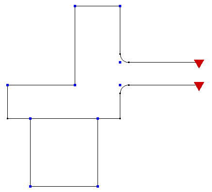
Figure 1: Two Part Sketch That Fails the 2D Meshing
The upper part is missing a line segment on the right side.
The red triangles mark the problem areas in the wireframe.