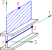
A beam element has two nodes. When a line representing a beam elements is drawn from one point to another, the first point is the "I" node and the second is the "J" node. A third point in space, the "K" node, provides the orientation of the cross-sectional properties. The K node is defined on the basis of the Surface number of the lines or it can be manually specified and applied to selected lines. The orientation scheme is as follows:
- Local axis 1 is in the direction from the I node to the J node.
- Local axis 2 is perpendicular to the beam element line, lies in the I, J, K plane, and is towards the orientation point (K node).
- Local axis 3 is the cross-product of local 1 and local 2 (also known as the right-hand rule).
The image below depicts a wide flange beam with the local 2 (weak bending) axis oriented in the +Z direction.
For the subject model, the lines are drawn in the correct location and the local 2 axis orientation is correct for every element. However, as seen on the prior tutorial page, the local 3 axis direction is wrong for the 7x4 angles comprising the X-brace in the lower portion of the tower. The only way to reverse the local 3 axis direction is to invert the I and J nodes for the appropriate beam segments. Here is how to do so:
- Click the
 FEA Editor tab above the browser to return to the FEA Editor.
 - Click
 Draw
Draw  Design Layer Control. The Layer Control dialog box displays.
 - Activate the checkbox in the Filter column for Layer 1. This will prevent the 8x6 angles from being selected while maintaining their visibility.
- Click in the display area to make that window active.
- With the
 Selection Select Lines mode active, press Ctrl-A to select all lines in layer 2.
 - With the
 Selection Shape Point or Rectangle mode active, hold down the Ctrl key, click, and drag to draw a selection box that tightly encloses the short horizontal member and the X-brace above it, as shown below. Be careful not to include any elements from the lower X-brace.
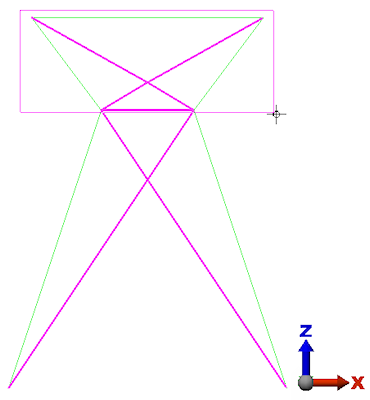
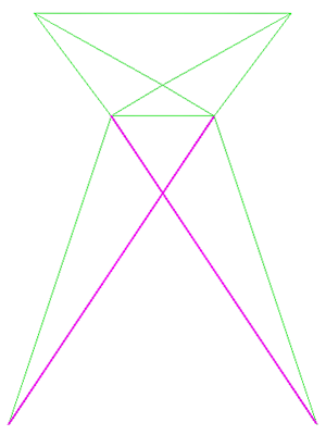
After releasing the mouse, the upper members are now deselected and only the lower X-brace remains selected, as shown below.
- With the
- Right-click in the display area and choose Beam Orientations Invert I and J Nodes.
- Press Esc to clear the selection set.
- Deactivate the checkbox in the Filter column for Layer 1.
- Click the Close button to exit the Layer Control dialog box.
- Click
 Analysis Analysis Check Model. The model will be validated and rendered within the Results environment.
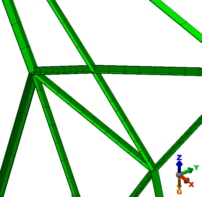
 - Use the mouse wheel to zoom in (rotate the wheel), to rotate the view (click the middle button and drag the mouse), and/or to pan the view (hold Ctrl while dragging the mouse with the middle button clicked). Carefully examine the orientation of the beams. They should now be consistent, as shown in the image below.
- Click
 View Appearance Visual Style Shaded with Features to return to the default visual style for the Results environment.
 - Click the FEA Editor tab above the browser to return to the FEA Editor.
We are ready to proceed with the application of constraints and loads.