Now we will apply the fixed boundary conditions to the static combs and the end of the moving comb.
- Click
 View
View  Navigate Orientation Top View.
 - With the
 Selection Shape Point or Rectangle and
  Selection Select Vertices commands active, click the node at the top of the vertical beam element (+Y end) as currently viewed (see image below).
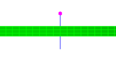
- Click
 Setup Constraints General Constraint.
 - Click the No Translation button.
- Click OK.
- With this node still selected, click
 Setup Constraints 1D Spring Support.
 - Activate the Rotation option under Type.
- Click the Y Direction option.
- Type 0.35 in the Stiffness field.
- Click OK.
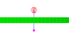
- Click the node at the bottom of the vertical beam element (-Y end) as currently viewed (see image below).
- Click Setup Constraints General Constraint.
- Activate the Tx and Tz options under Constrained DOFs.
- Click OK.
- Click
 View Navigate Orientation Back View.
 - With the
 Selection Select Surfaces command active, select the face of the ring at the outside diameter of the motor, as shown highlighted below (yellow on green).
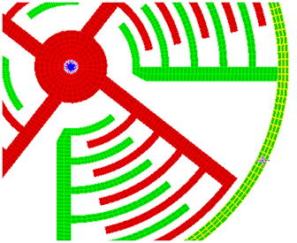
- Click Setup Constraints General Constraint.
- Click the Fixed button.
- Click OK.