Next, add the beam elements to the top surface of the knob. We will create four radial spokes and a 1.5" long axial beam element. These will be used later to apply a torque moment to the knob.
- Click the heading for Part 1 in the browser (tree view).
- Holding down the Ctrl key, also select the heading for Part 2 in the browser.
- Right-click one of the selected headings and deactivate the Visibility option.
- Press <Esc> to clear the parts selection. Only the knob (Part 3) should remain visible.
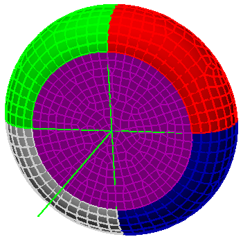
- To make the individual surfaces of the knob easier to see, click
 View
View  Appearance Color by Surface. This makes the vertices to which we will attach beam elements easier to identify.
 - Click
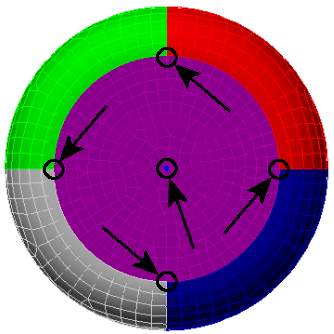
 View Navigate Orientation Back View. The model will appear as shown below. The arrows indicate vertices to which we will be attaching the endpoints of radial beam elements in step 5 on this page.
 - Click
 Draw Draw Line. Clear the Use as Construction check box. Notice that the first available, unused part number of 4 has automatically been selected.
 - Activate the Single Line check box. We will first add the four radial beam element. The Single Line option creates separate lines. Otherwise the endpoint of one line would become the starting point for the next line (creating a chain of line segments).
- Click the construction vertex at the center of the surface.
- Click the node at the 12 o'clock position along the perimeter of the circular flat surface to create a radial line.
- Click the construction vertex again.
- Click the node at the 3 o'clock position to create a second line.
- Click the construction vertex again.
- Click the node at the 6 o'clock position to create a third line.
- Click the construction vertex again.
- Click the node at the 9 o'clock position to create a fourth line.
- Next, we add the axial beam element. Once again, click the construction vertex at the center of the surface.
- Activate the Use Relative check box. The next coordinates entered will be relative to the last point rather than absolute coordinates.
- Type 1.5 in the DY: field and press Enter. This will create an outward beam element along the axis of the knob.
- Press the Esc key to exit the line command.
- Click the middle mouse button and drag slightly to rotate the view so that all five beam elements can be seen. The model should look similar to the image below.
- Click the heading for Part 1 in the browser.
- Holding down the Ctrl key, also select the heading for Part 2 in the browser.
- Right-click one of the selected headings and activate the Visibility option to show these two parts.
- Press Esc to clear the selection.
- Click the
 Home icon immediately above the ViewCube for an isometric view of the model. Note: The Home icon will not be visible until the cursor is at or near the ViewCube.
 -
Click
 View Appearance Color by Part to restore the view to the default Color by option. The model should appear as shown below.
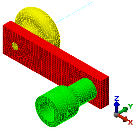
This tutorial is now complete. The meshed model can be used to complete the Crank Static Stress Analysis tutorial.