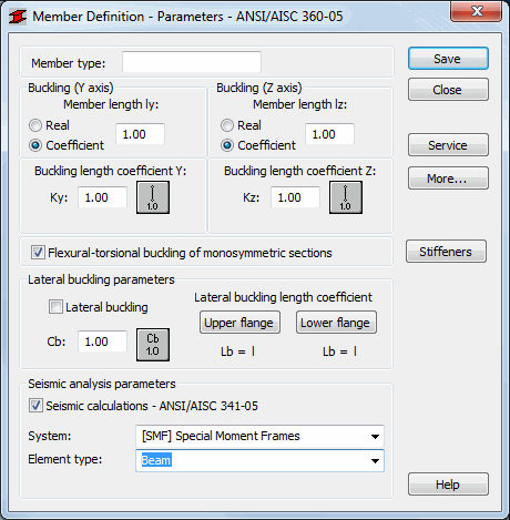
The Member Type Parameters dialog defines parameters of the member type for the American steel code ANSI / AISC 360-05. Access the parameter by clicking the New member type option in the Member Type dialog or by clicking the Parameters button in the Definitions dialog dialog. The following dialog displays:
The following parameters are defined in the dialog:
- Member Type: The name of a selected member type (any name of the member type may be entered into this field).
- Buckling (Y axis) or (Z axis): Defines the length of a member for the appropriate plane.
- There are two ways to define this length:
- Click Real, enter a value for the member length.
- Click Coefficient, enter a coefficient by which the real member length should be multiplied to obtain the required value. For instance, if the value 0.25 is entered, it means that the relevant length equals 1/4 of the real length. Use this method to define simultaneously several members whose real lengths differ, while additional supports, for example, are equally spaced. If the parameters set are to be saved as a category, it is necessary to define the length this way. If the value 1.0 is entered, it guarantees that the actual length will be adopted for each member defined as Ly using the category.
- Buckling Length Coefficient (Ky and Kz): Defines member buckling length coefficients in both directions. The actual member length (or the sum of the component member lengths) is entered automatically to the appropriate fields.
- The buckling length coefficient depends on the end-support conditions of the member nodes in the buckling plane. The member buckling length may also be defined in the Buckling Diagrams dialog, opened by clicking the icon representing a selected type of the member buckling model. It includes typical diagrams of member support; when one is selected, the coefficient value will be accepted or calculated automatically.
- The icons in the dialog are divided into two groups: the first contains typical (code) methods of member support and the corresponding values of buckling coefficients, whereas the second contains icons of options used for calculating the buckling coefficient for columns of multi-story frames.
- Lateral Buckling Parameters (Lb and Cb): Defines the options used during verification of the lateral buckling of the member. You can access the options by clicking the relevant icon.
- Lateral buckling coefficient Cb: Adopted as specified in the guidelines provided in Section F1. Selection of the middle icon indicates that the value Cb is calculated according to the formula F1-1 from the code. Lateral buckling calculations require providing for the member the distance between sections protected against torsion - the lateral buckling length. It is necessary to distinguish two lateral buckling lengths as the upper or lower flange can be fixed separately and the compressive stress may occur in the upper or lower flange for different load cases. Therefore, a value of the coefficient is given by which the base member length should be multiplied to obtain the lateral buckling length. The length l is taken as the base length. It is possible to enter the coefficient value directly or select the icon representing a typical fixing case for which the coefficient will be automatically chosen.
- Lateral buckling: when selected, then lateral buckling verification will be performed during the code calculations of steel members.
At the bottom of the dialog is the Seismic calculations - ANSI/AISC 360-05 option. After you select it, the software checks additional conditions to be satisfied by steel load-carrying elements subjected to seismic loads during the steel design. A set of regulations to comply with for seismic loads is based on the code ANS/AISC 341-05 - 'Seismic Provisions for Structural Steel buildings - Including Supplement No.1'. The check of steel elements of a seismically-loaded structure includes the verification of steel sections according to the previously-implemented American steel code ANSI/AISC 360-05 - 'Specification for Structural Steel Buildings' applying additional limitations given in ANS/AISC 341-05 - 'Seismic Provisions for Structural Steel Buildings'.
After you select Seismic calculations - ANSI/AISC 341-05, the following options become accessible:
- System - a field to select a seismic system type
- Element type - a field to select a bar type (for example, BEAM, COLUMN, BRACING, etc.).
If you select the STMF system, the additional option Special segment displays in the dialog; and if you select the OCBF system, the additional option is OCBF above Seismic Isolation Systems.
Click the More button to access an additional dialog for definition of member type parameters specified in the code.
Click the Service button to open an additional dialog for definition of member type parameters (limit displacements, initial deflections).
Click Save to add the member type with the defined name and parameters to the list of previously defined steel member types.