Use this dialog to define the parameters to apply during the verification of a steel member according to the ANSI/AISC 360-05 or ANSI/AISC 360-10 code.
Access
- In the Steel/Aluminium design layout, click Configuration in the Calculations dialog.
Dialog elements
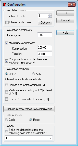
- Calculation points
- Specify a number of calculation points or characteristic points:
- Enter the number of points that are evenly distributed along the member length.
- Select Characteristic points and then click Options to open the Calculations in Characteristic Points dialog.
- Calculation parameters
-
- Efficiency ratio
- Enter the efficiency ratio to determines the factor by which the yield point will be multiplied. Doing this will increase or decrease of the yield point.
- Maximum slenderness
- Verifies the slenderness of the member for both compression members and tension members.
- Components of complex members are not taken into account
- Ignores complex members components for the members during the calculations.
- Calculation methods
-
- LRFD
- Performs the code calculations according to Section B3.3.
- ASD
- Performs the code calculations according to Section B3.4.
- Alternative verification methods
- If the Member verification according to Section H2 option is selected, the member is checked in terms of stresses according to Section H2. In such case the provisions of Section H1 are not taken into account.
- After activating the "Tension field action" for shear according to Section G3 option, the program will apply formulas given in Section G3 while evaluating the shear strength V n . If the conditions for the use of 'Tension field action', given in Section G3.1, are not satisfied by the section, the shear strength is evaluated according to Section G2.
- Exclude internal forces from calculations
- Opens the - Internal forces not taken into consideration dialog which allows you to set the limit values of internal forces, and to present the results of the member design..
- Moreover, units for presenting results of the member design can be selected here. The results are presented in the units used in the indicated steel code, or in the units used in Robot.
- Units of results
- Specify if you want to use the Russian steel code units or the units used in Robot in your member design results.
- Camber
- Select Take the deflections from the following case into consideration, and then select the load case for which the displacements defined will be treated as structure camber.