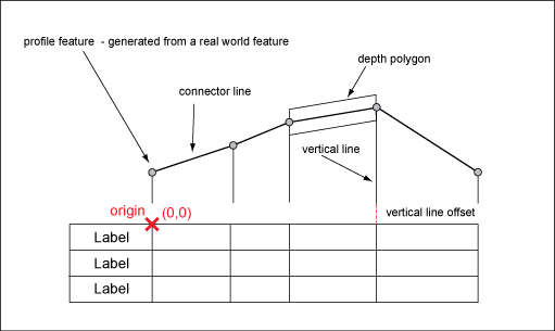
Use profiles in Oracle-based enterprise industry models to generate three dimensional views of utility features, for example, in the Wastewater, Water or Gas industry models. Based on the profile data structure, you can create your own profile definitions in any industry model to draw longitudinal profiles of any linear feature class. Use profiles for objects such as pipes, by projecting features onto an axis. The axis can be selected in the drawing or it can be defined through network tracing.

Profile feature classes store the profile drawing.
Profiles provide a detailed view of the network. You can query network information by selecting a feature in the profile or in the drawing. Profiles are stored in a local spatial reference system, with 0,0 as the base coordinates. These coordinates can be placed anywhere in the global coordinate system. In order to create a profile, profile features are calculated and stored in the industry model. All features and feature classes can be edited and styled using the Display Manager.
Create Profile Definitions
The profile definitions are available in AutoCAD Map 3D in the Profile Manager. In the Profile Manager, you can select the definition, modify the default settings, select the features and the profile axis, and create and store the profiles.
When you create a profile definition from scratch, the profile explorer helps you to review the profile feature classes and their relations. See also Profile System Tables.
You can save a profile definition as template, and reuse the template for modifications. The system stores the profile definition templates in the system tables TB_*_TPL.
- TB_PRO_DEFINITION_TPL
- TB_PRO_DETAIL_TPL
- TB_PRO_SUB_DETAIL_TPL
In AutoCAD Map 3D, use the Profile Manager to create and draw profiles using the profile definitions. See “Working with Profiles” in the User's Guide.
Create Profile Feature Classes
Profile feature classes store the points, lines, and labels for each profile. Profile feature classes represent two types of features:
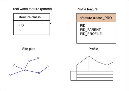
A real world feature (parent), such as a manhole cover. Each real world feature corresponds to a profile feature. Real world features are profile objects that are normally displayed in the global reference system. The profile feature class stores the relation to the real world feature in the attribute FID_PARENT.
Decoration elements of the profile drawing, such as frame lines, legend, and fix labels. Decoration elements do not correspond to any real world features.
For example, a profile feature of WW_LINE_PRO stores the profile line that corresponds to a real world feature of WW_LINE.

Use the Data Model administrator to create the profile feature classes. Usually you have one corresponding profile feature class for each real world feature class. The following table is an example of how a wastewater profile could be stored.
| Profile component | Profile feature class (example) | Level of detail |
|---|---|---|
| Network line | WW_LINE_PRO | detail |
| Network point | WW_POINT_PRO | detail |
| Feature label | WW_LINE_PRO_TBL WW_POINT_PRO_TBL |
sub detail |
| Vertical line | WW_PROFILE_LINE_PRO | detail |
| Connector line | WW_PROFILE_LINE_PRO | detail |
| Symbol such as origin, reference height | WW_PROFILE_POINT_PRO | detail |
| Polygon | WW_PROFILE_POLYGON_PRO | detail |
| Static text such as height, legend labels | WW_PROFILE_STATIC_TEXT | detail and sub detail |