We will compare some basic styles with more complicated styles within a single drawing and also compare a drawing template (.dwt) with a sample drawing. This exercise will help illustrate how some of the basic styles compare to a drawing that has undergone style additions and revisions. When starting out with AutoCAD Civil 3D, focus on the layout and use of the Toolspace Settings and Prospector tabs as they are critical components for style creation, control, and identification.
Surface Style Comparison
Open the sample styles drawing, Sample_styles.dwg, in C:\Program Files\AutoCAD 2015\C3D\Help\Civil Best Practices Guide. The surface styles are designed to display different components of a surface at different design stages. The surface style assigned to the drawing is called Existing Ground Contours. This is an example of a style that would be used during the design stage of a project.
In the Surface Style - Existing Ground Contours dialog box, the Border, Major Contour, and Minor Contour components are set to visible. These components determine how the surface appears in the drawing. With these components enabled, the surface is displayed as shown in figure 6.
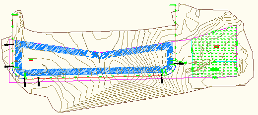
Figure 6: Levels and slopes are not visible
The following exercise demonstrates how to change the Existing Ground Contours style so that it reflects the Final Gradient style. Editing the contour style will demonstrate how to experiment with styles to suit your requirements.
To change the Existing Ground Contour style
- On the Toolspace Settings tab, expand the Surface styles collection and double-click the Existing Ground Contours style.
- On the Display tab, click the light bulb icons to turn off the Major Contour and Minor Contour components.
- Click the light bulb icons to turn on the visibility for the Levels and Slope Arrows components as shown in figure 7. Keep the Border contour set to Visible.
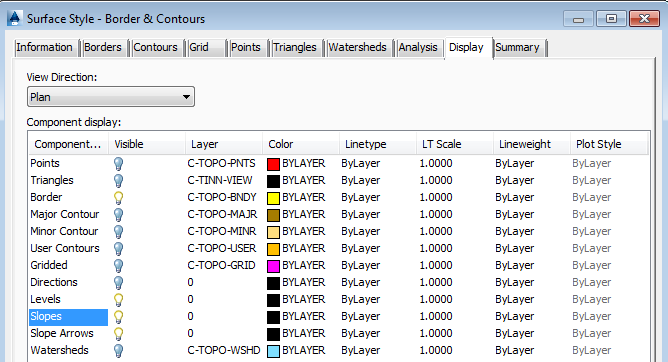
Figure 7: Enable the levels and slopes components
Now the drawing displays borders, level differences indicated by color, and slope direction arrows and appears as shown in figure 8. The contour lines are no longer visible. These changes now reflect the components that are enabled for the supplied Finish Gradient surface style.
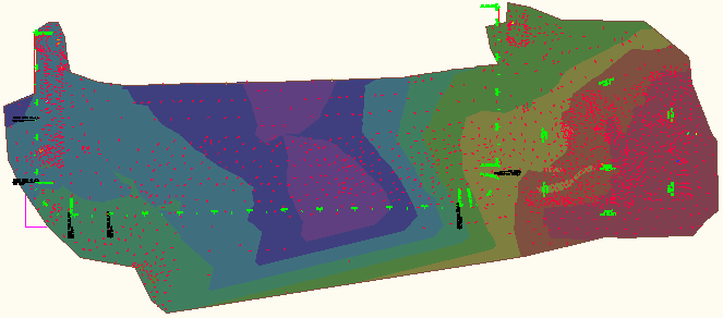
Figure 8: Level colors and slope arrows for presentation
The Finish Gradient style is set up to display the drawing for presentation purposes or for the latter stages of a project.
Before setting up your styles you should explore the existing styles to determine what would work best for you. Remember that seemingly small style property edits can have dramatic effects in your drawings.
Take a conservative approach when creating styles and make additional changes only as warranted.
Plot Style Comparison
For plot styles, you can assign colors to differentiate between various types of plot components.
To explore plot styles
- In the Sample_styles.dwg, on the Toolspace Settings tab, in the Plot collection, expand the Plot Styles collection and right-click Residential. Click Edit.
- In the Plot Style - Residential style dialog box, on the Display tab, the color of the plot segments is set to blue.
Observe that the plot area fill component is visible and note the hatch pattern that is set for the plot area fill.
- Look at how another plot style is composed. Click Application Menu
 New. In the dialog box, select _AutoCAD Civil 3D (Imperial) NCS.dwt.
 - Observe how the style for Single-Family plots is set up differently. Specifically, the assigned color is different and the plot area fill is not visible. The hatch patterns for these plot styles are also different. If you click on the hatch pattern, the Hatch Pattern dialog box is displayed, where you can change the assigned hatch pattern.
The different hatch patterns for each of these styles shows one example of how different variables and combinations are possible when creating new styles or modifying existing ones.
Style Suggestions
While learning to use AutoCAD Civil 3D styles, consider the following:
- Start out with as few styles as possible until you become more comfortable with the product.
- Track your new styles so that you can keep them straight until you can remember the visible indications for each one.
- Take time to explore the wide range of style components and options. You may discover useful aspects of the tools that are not readily apparent.
-
Only create new styles as you need them. Remember that styles should serve your designs, and are tools to help improve your drawings and facilitate the process. They should not make your job more difficult. Once you become accustomed to their use and how they are created, copied, and edited, the application of styles will greatly enhance your drawings and make your job easier.