In profile view, you can add pipes and bends, as well as individual pipes, bends, and ancillaries.
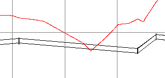
Adding pressure network parts in the profile view is part of a workflow you may use for designing around vertical obstacles or cases where the required depth is not obtained. For example, if you review your design in profile and see that part of a pipe comes above the surface, such as in the following image, you can break the pipe into segments and delete the section that is above the surface. You can then re-draw the pressure network parts to go below the surface using the Pressure Network Profile Layout tools.

When using the Pipes & Bends or Add Pressure Pipe option to add parts in profile view, you will be prompted to select the part you want to start drawing from and the part to connect to (the start and end parts of the range). The parts must be co-directional, meaning that their open ports must be facing each other. If it is detected that these parts may not connect together correctly in plan view, an alert message is displayed suggesting that the design be edited in plan view first in order to establish the correct network path.
Adding Pipes, Bends, and Ancillaries in Profile View
- Parts that you add with the Pipes & Bends command are constrained to the available angles in the parts list.
- Pipes that you add with the Add Pressure Pipe command are not constrained to available angles in the parts list.
- You can add vertical bends using the Add Bend command. Bends, but not tees and crosses (the other types of fittings available in the default pressure network catalogs) can be added to a profile view. Note: In profile view, bends can be added only to open connections on pressure pipes. They cannot be inserted along a pressure pipe or added to open connections on other fittings or ancillaries.
- You can add ancillaries using the Add Ancillaries command. Note: In profile view, ancillaries can be added to open connections on pressure pipes, fittings, or other ancillaries. They cannot be inserted along a pressure pipe.