An assembly set is a group of assemblies used to create a corridor in a junction object.
Assembly sets are used only with junction object creation. A default assembly set is included with AutoCAD Civil 3D. You can create a junction using this default assembly set, or you can create your own custom assembly sets to suit the needs of specific junction design.
When you apply the assembly set, and create or update the junction object corridors, the referenced assembly objects are imported into the current drawing, if they are not already there.
The following table describes the components that are associated with an assembly set:
| Component | Description |
|---|---|
| assembly set | A group of assemblies that have been designed for use in specific type of junction design. An assembly set is defined in an assembly set file. |
| assembly set file | An .xml file containing information that defines the assemblies that are included in an assembly set. An assembly set file contains the names of the assembly objects, the location (path) where the individual assembly drawings exist, and other information about the assemblies included in the set. This .xml file serves primarily as a pointer (reference mechanism). It does not contain the actual assembly drawing data. |
| assembly object names | The name of each assembly object referenced in the set is maintained in the assembly set file. Note that the assembly object data itself is not contained in the assembly set file, just the information that enables AutoCAD Civil 3D to locate the assembly object data (a reference to the assembly name, and the name of the drawing file that contains the assembly object.) |
| assembly drawings | Each assembly object referenced in an assembly set is also saved to an assembly drawing file. An assembly drawing file contains a single assembly object. The assembly drawing file typically has the same name as the assembly object. For example, the assembly drawing file for an assembly object named Secondary_Road_Half_Section _Daylight_Left is named Secondary_Road_Half_Section _Daylight_Left.dwg. The assembly drawing file associated with each assembly object referenced in the assembly set is also stored (referenced) in the assembly set. |
The fist time you use the Create Junction wizard, it is recommended that you accept and use the assembly set that is referenced by default on the wizard. As you become more familiar with creating junctions, you will want to create your own customized assembly sets.
The assembly set that is included with AutoCAD Civil 3D is typically located by default in the following location:
C:\ProgramData\Autodesk\C3D <version>\enu\Assemblies\<units>
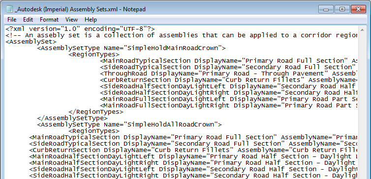
The following illustration shows the contents of the default assembly set file that is included with AutoCAD Civil 3D.

Modifying Assemblies Referenced in Assembly Sets
It is important to note that if you modify an assembly that is referenced in an assembly set, and that is already used in the current drawing, and you do not change the name of the modified assembly, this does not change the junction area corridor definition.
In such cases, if you try to create a new junction, or recreate an existing junction, the junction corridor will continue to use the assembly of the same name in the current drawing, and will not use the modified assembly that is referenced in the assembly set folder.
If you want to apply the updated assembly that is referenced in the assembly set to the junction corridor, you must delete (or rename) the assembly with the same in name in the current drawing first.