The Spring object takes the form of a coiled spring that lets you simulate a flexible spring in animations. You can specify the overall diameter and length of the spring, the number of turns, and the diameter and shape of its “wire.” When you attach the spring to two "binding" objects, it follows their motion.
Procedures
To create a spring:
- Drag and release to specify the outside diameter.
- Move the mouse and click to specify the overall length of the spring.
To use a spring in a dynamics simulation:
- Bind two objects to the ends of the spring, and choose Bound to Object Pivots in the End Point Method group box at the top of the command panel.
- In the dynamics simulation, add the spring to the Object List. (The spring itself is not adjustable in the dynamics Edit Object dialog, so all of the dynamics parameters will be disabled for the spring object.)
- Include at least one of the bound objects or a parent of one of the bound objects in the simulation. For example, you can bind the ends of a spring to two dummy objects, and one of the dummies can be the child of an object that’s included in the simulation. The dummy without a parent will be stationary and the spring will pass its force through the other dummy to its parent. Note: Spring is an "ideal" object with no mass. While it can be used in dynamics simulations, it cannot participate directly in collisions or effects. A spring can only exert force on other objects in simulations. As a result, when you assign a spring object to a dynamics simulation, and then view it in the Edit Object dialog, all of the parameter settings are disabled.
The following must be in place to use the spring forces in a dynamics simulation:
Interface
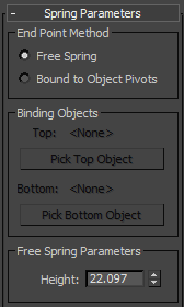
Spring Parameters rollout

End Point Method group
- Free Spring
-
Choose this when using the spring as a simple object that’s not bound to other objects or used in a dynamics simulation.
- Bound to Object Pivots
-
Choose this when binding the spring to two objects, using the buttons described next.
Binding Objects group
Use these controls to pick the objects to which the spring is bound. "Top" and "Bottom" are arbitrary descriptors; the two bound objects can have any positional relationship to each other. To complete the binding, select two binding objects, and then click Bound to Object Pivots.
Each end point of the spring is defined by the center of the overall diameter and the center of the wire. This end point is placed at the pivot point of the object to which it is bound. You can adjust the relative position of the binding object to the spring by transforming the binding object while the Affect Object Only button is turned on in the Hierarchy  Pivot panel.
- Top (label)
-
Displays the name of the "top" binding object.
- Pick Top Object
-
Click this button and then select the "top" object.
- Bottom (label)
-
Displays the name of the "bottom" binding object.
- Pick Bottom Object
-
Click this button and then select the "bottom" object.
Free Spring Parameters group
- Height
-
Use this field/spinner to set the straight-line height or length of the spring when it is not bound. This is not the actual length of the spring's wire.
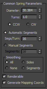
Common Spring Parameters group

- Diameter
-
The overall diameter of the spring, as measured at the center of the wire. (The diameter of the wire itself has no effect on this setting.)
- Turns
-
The number of full 360-degree turns in the spring.
- CCW/CW
-
Specifies whether the coils of the spring are counterclockwise (CCW) or clockwise (CW).
- Automatic Segments
-
Choose this option to force each turn of the spring to contains the same number of segments, as specified in the Segs/Turn spinner. Thus, if you increase the number of turns, the number of segments also increases.
- Segs/Turn
-
This spinner lets you specify the number of segments in each 360-degree turn of the spring.
- Manual Segments
-
When this option is chosen, the length of the spring contains a fixed number of segments, no matter how many turns in the spring. Thus, as you increase the number of turns, you must manually increase the number of segments to maintain a smooth curve.
- Segments
-
This spinner lets you specify the total number of manual segments in the spring.
- Smoothing
-
Provides various methods of smoothing the object. The options here work the same as those in the Torus primitive.
- All All surfaces are smoothed.
- Sides Smoothing runs along the length of the wire, but not around its perimeter.
- Segments Smoothing runs around the perimeter of the wire, but not along its length.
- None No smoothing is applied.
- Renderable
-
When on, the object appears in the rendering; when off, the object does not appear.
- Generate Mapping Coords
-
Assigns mapping coordinates to the object. Default=on.
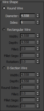
Wire Shape group

Provides three different types of wire cross-sections for the spring: round, rectangular, or D-shaped. Each type has its own set of parameters.
- Round Wire
-
Specifies a round wire for the spring.
- Diameter The diameter of the wire.
- Sides The number of sides that make up the cross section.
- Rectangular Wire
-
Specifies a rectangular wire.
- Width Determines the width of the cross section.
- Depth Determines the depth of the cross section.
- Fillet When combined with Fillet Segs (below), this lets you fillet (round) the corners of the cross section.
- Fillet Segs Specifies the number of segments in the fillet.
- Rotation Rotates the angle of the cross section along the entire length of the spring.
- D-Section Wire
-
Specifies a D-shaped wire.
- Width Determines the width of the cross section.
- Depth Determines the depth of the cross section.
- Round Sides Specifies the number of segments that make up the rounded side of the D-shape.
- Fillet When combined with Fillet Segs (below), this lets you fillet (round) the corners of the cross section.
- Fillet Segs Specifies the number of segments in the fillet.
- Rotation Rotates the angle of the cross section along the entire length of the spring.