The Sweep Parameters rollout has various controls for how to construct the swept geometry.
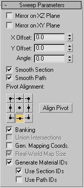
- Mirror On XZ Plane
- When turned on, the section is flipped vertically in relation to the spline to which the Sweep modifier is applied. Default=off.
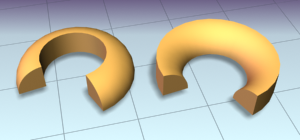
Left: The object shows the default state.
Right: The object has Mirror On XZ Plane turned on.
- Mirror On XY Plane
- When turned on, the section is flipped horizontally in relation to the spline to which the Sweep modifier is applied. Default=off.
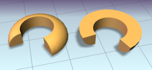
Left: The object shows the default state.
Right: The object has Mirror On XY Plane turned on.
- X Offset
- Lets you shift the horizontal position of the section relative to the underlying spline.
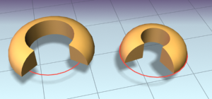
Left: The section is in the default position.
Right: The section is offset –10 relative to the underlying spline path (red).
- Y Offset
- Lets you shift the vertical position of the section relative to the underlying spline.
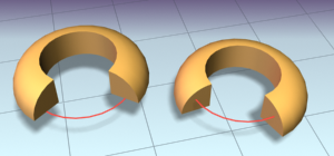
Left: The section is in the default position.
Right: The section is offset –10 relative to the underlying spline path (red).
Note: The X and Y Offsets let you fine tune the section position while the Pivot Alignment settings allow for a quick initial adjustment. - Angle
- Allows you to rotate the section relative to the plane on which the underlying spline is located.
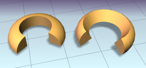
Left: The section is in the default position.
Right: The section is rotated 30 degrees.
- Smooth Section
- Provides a smooth surface around the perimeter of the section that is swept along the underlying spline. Default=on.
- Smooth Path
- Provides a smooth surface along the length of the underlying spline. This type of smoothing is useful when for curved paths. Default=off.
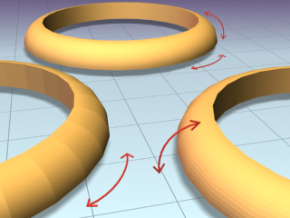
Left: Smoothing the path
Right: Smoothing the section
Rear: Smoothing both path and section
- Pivot Alignment
- This is a 2D grid that helps you align the section to the underlying spline path. Selecting one of the nine buttons shifts the section's pivot around the spline path. Note: When none of the Pivot Alignment buttons is depressed the pivot point of the section is used as the alignment point.
- Align Pivot
- When turned on, a 3D representation of the Pivot Alignment grid appears in the viewport. You only see the 3x3 alignment grid, the section and the underlying spline path. Once you're satisfied with the alignment, turn off the Align Pivot button or right-click to see the sweep.
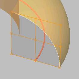
Align Pivot grid showing control points (in orange) superimposed over a duplicate sweep.
- Banking
- When on, sections rotate about the spline path whenever the path bends and changes height in the path's local Z axis. Banking is ignored if the spline path is 2D. When off, shapes do not rotate about their Z axis as they traverse a 3D path. Default=on.
- Union Intersections
- If working with multiple intersecting splines, like a grid, turn this switch on to produce cleaner intersections with fewer artifacts. Note: Union Intersections takes additional time to compute the intersections, so leave this switch off if you don't have intersecting splines. Furthermore, this setting will only calculate intersections of separate splines contained in one shape object. So a figure X (separate, intersecting splines) will be properly intersected, but a figure 8 (a single, self-intersecting spline) will not.
- Gen. Mapping Coords
- Applies mapping coordinates to the extruded object. Default=off.
- Real-World Map Size
- Controls the scaling method used for texture mapped materials that are applied to the object. The scaling values are controlled by the Use Real-World Scale settings found in the applied material's Coordinates rollout. Default=on.
- Generate Mapping IDs
- Assigns different material IDs to the sides and the caps of the sweep. Specifically, if both Use Section IDs and Use Path IDs are both turned off the sides receive ID 3, the front cap receives ID 1, and the rear cap receives ID 2. Default=on.
- Use Section IDs
- Uses the material ID values assigned to segments of the section that is swept along the underlying spline or NURBS curve. Default=on.
By applying an Edit Spline modifier to a Custom Section, different material IDs can be assigned to each segment that makes up the section.
Note: Built-in sections do not benefit from the Use Section IDs switch. - Use Path IDs
-
Uses the material ID values assigned to segments of the underlying spline or curve sub-objects in the underlying curve.
By applying an Edit Spline modifier to the underlying spline, each segment can be assigned its own material ID.
Note: Use Section IDs and Use Path IDs does not control the material IDs of the front and rear caps of the sweep.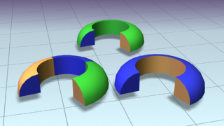
Left: Materials set by path IDs
Right: Materials set by section IDs
Rear: Section and Path IDs turned off