Defining the part geometry is generally the first step in the development of a finite element model.
Here, the plate geometry is sketched and extruded to generate a solid part.
- Open Abaqus/CAE. Some of the screenshots presented in this tutorial were taken from older versions of Abaqus. Consequently, results and images may differ slightly for other versions of CAE.
- Create a new part () and select 3D, Deformable, Solid, and Extrusion as options. Name the part Plate.
- Create a rectangle () with the starting corner at 0, 0 and the opposite corner at 1.5, 6.
- Create a circle () with the center point at 0.75, 3 and the perimeter point at 0.75, 3.125.
- Extrude the part to a depth of 0.144.
- Create datum planes () using the Offset from principal plane method.
- Offset the first plane 0.75 from the YZ Plane.
- Offset the second plane 3 from the XZ Plane.
- Offset the third plane 2.25 from the XZ Plane.
- Offset the fourth plane 3.75 from the XZ Plane.
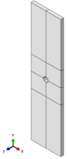
- Partition the part () using the four datum planes created in Step 6. The part should appear as shown in below.
The plate needs to be partitioned to assign edge seeds during meshing.