Create the mesh on the part geometry.
Since the plies are unidirectional and are loaded in bending, a single layer of C3D8I elements are used for each of the plies. COH3D8 elements are used for the cohesive elements. The mesh will be edited to adjust the cohesive layer thickness to the recommended value of 0.0.
- Switch to the Mesh module.
- Click and select all regions of the beam. Change the mesh Technique to Sweep and redefine the sweep path for all three cells so that the sweep direction is in the global positive Y-direction.
- Select and seed the edges by number so that there are 12 elements in the width direction, 100 elements in the length direction, and 1 element per cell in the thickness direction.
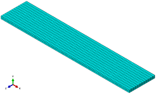
- Mesh the part. The mesh should appear as shown below and consist of 3,600 elements.
- Assign () C3D8I elements to the ply sections and COH3D8 elements to the cohesive section.
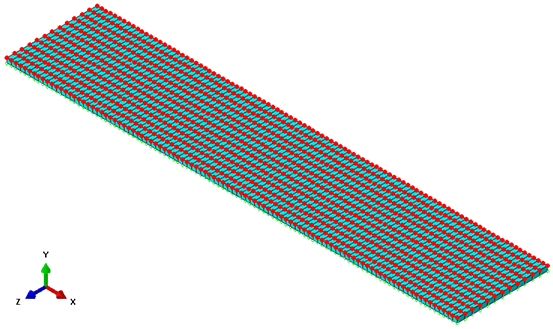
- Select and choose Node as the category and Edit as the method. Choose the nodes that lie on the positive XZ-face of the cohesive layer as shown below. There should be a total of 1,313 nodes selected. Click Done in the viewport.
- Tip: Use the Display Group tools to hide the top cell and allow for easier selection of cohesive layer nodes.
- In the Edit Nodes dialog box, choose Offsets as the specification method, un-select the Project to geometry option, and enter a value of -0.0001 in the 2-direction. Click OK.
- Verify the cohesive layer does not have a thickness by zooming in on the region.
Note: The edited cohesive layer thickness is only visible when the mesh is shown. If the mesh is not active in the viewport, the original geometry is shown.