Apply boundary conditions that constrain the tank during the pressure loading.
- Switch to the Load Module.
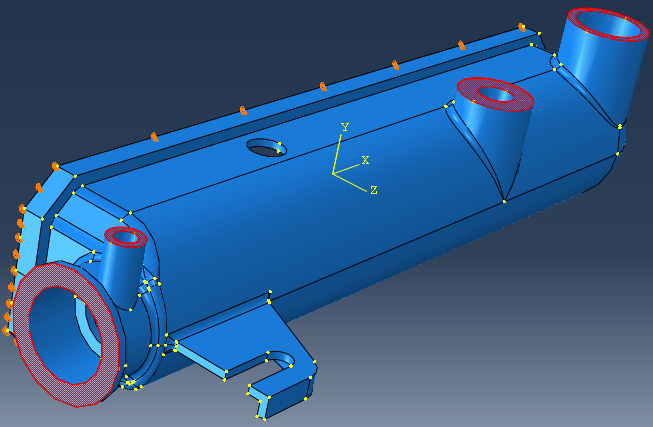
- Create a boundary condition () to constrain the displacement of the tank base.
- Set the step to Initial and select Displacement/Rotation. Click Continue.
- Use the viewport to select the six surfaces on the base of the tank and click Done.
- Select U1, U2, and U3. Click OK.
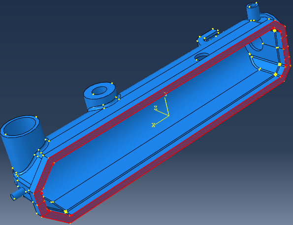
Now create an additional displacement constraint to further constrain the model.
- Click and again set the step to Initial and select Displacement/Rotation. Click Continue.
- From the viewport, select the four surfaces shown below and click Done.
- Select U1, U2, and U3. Click OK.