Defining the part geometry is generally the first step in the development of a finite element model.
Here, the plate geometry is sketched and extruded to generate a solid part.
- Open a new instance of Abaqus/CAE. (Some of the screenshots presented in this tutorial were taken from older versions of Abaqus. Consequently, results may differ slightly for other versions of CAE.)
- Create a new part () that has the options: 3D, solid, deformable, and extrusion.
- Sketch a rectangle () with the starting corner located at coordinates 0, 0 and the opposite corner located at 150, 3.
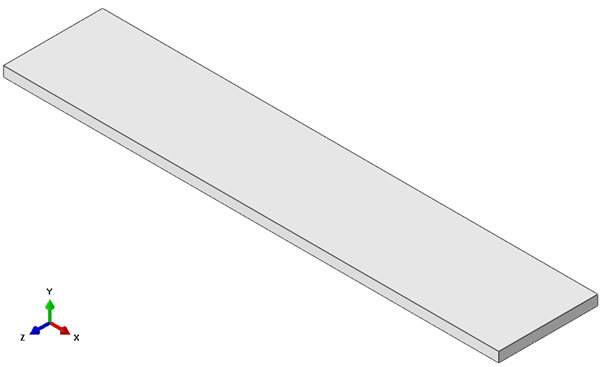
- Extrude the base sketch to a depth of 30. The part should appear as shown below.
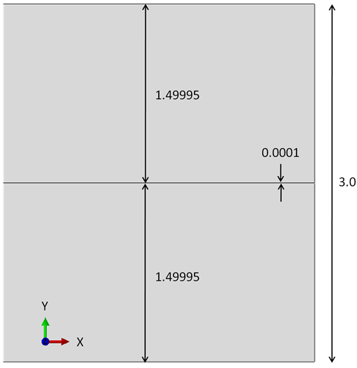
- The cohesive layer will initially require a finite thickness (0.0001 in this example) for model creation purposes, but will later be modified (via a mesh edit) to have a thickness of 0.0. To form the cohesive layer, the beam is partitioned using datum planes. Create one datum plane () offset 1.49995 from the top XZ-face and a second datum plane offset 1.49995 from the bottom XZ-face.
- Recall, the cohesive layer thickness is 0.0001 and the beam thickness is 3. Therefore, 1.49995 = (3-0.0001) / 2.
- Use the datum planes to partition () the beam into three cells. A side view showing the partitioned beam is shown below.