Use the Simulation Composite Analysis plug-in interface to choose from a variety of material and analysis options.
The material and analysis options include the following:
- Selection of a composite material to use in the analysis (Simulation Composite Analysis-compatible material definitions must be created outside of ANSYS using Composite Material Manager).
- The choice of four unit systems
- Selection of the principle material direction
- Inclusion of progressive failure in the analysis
- Method of calculation of the failed plain weave properties
- Inclusion of hydrostatic pressure induced material strength enhancement
- Stiffness degradation method (instantaneous or none)
- Inclusion of pre failure nonlinearity
- Setting the matrix and fiber constituent stiffness post-failure degradation ratios
- Creating additional output variables that provide fiber and matrix constituent stresses and strains
Using these options, you can tailor your analysis to the requirements of the problem. For a detailed discussion of the options available, refer to the Simulation Composite Analysis User's Guide.
In the following steps, a user-material is created for the plate, and progressive failure analysis is requested using the Simulation Composite Analysis GUI.
- Click the COMPOSIT button from the ANSYS Toolbar and select Create Composite Material. The Simulation Composite Analysis plug-in appears.
Note: the COMPOSIT button only works in the model creation preprocessor (/PREP7).
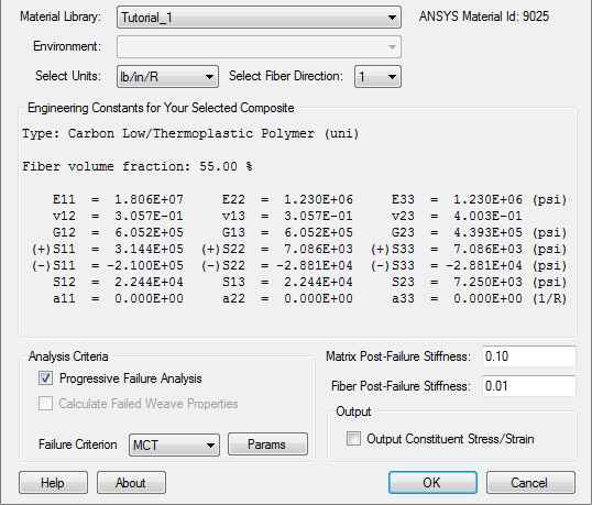
- From the Material Library list, select the material you created in the previous section, Tutorial_1.
The unit dependent Engineering Constants specific to this material are listed in the plug-in for you to review. Note the ANSYS Material ID (matID) corresponding to this material is also shown in the dialog box. This value may vary from computer to computer. It is useful to know the Material ID when working with input files since ANSYS uses the matID to identify Simulation Composite Analysis materials.
- Since this model uses inches and pounds as base units, select lb/in/R from the Select Units list.
There are 4 unit systems to choose from. The default unit system is N/m/K.
- Select 1 as the fiber direction.
2 can also be used as the fiber direction, but it would require a different composite layup orientation than the 1 direction. As a general rule, it is recommended that 1 be used as the fiber direction to maintain consistency from model to model. On occasion, however, it will not be possible to create an orientation in ANSYS that allows for the 1 direction to be the fiber direction due to the combination of complex model geometry and orientation limitations. In such cases, it may be necessary to use the 2 direction as the fiber direction.
- Select Progressive Failure Analysis, the foundation component of Simulation Composite Analysis.
- Set the Matrix Post-Failure Stiffness value to 0.10 and the Fiber Post-Failure Stiffness value to 0.01. The plug-in should appear as shown below.
These values specify the ratio of damaged to undamaged material properties for the material. For example, a value of 0.01 for the Fiber Post-Failure Stiffness means that when an integration point undergoes a fiber failure event, the material properties at that integration point will degrade to 1% of the undamaged properties.
- Click OK.