In the experimental testing, a cylindrical roller was used to load the specimen. As a result, only the edge of our rubber pad experiences a direct loading.
The specimen is loaded using imposed displacements because it results in a much more gradual failure process than a comparable loading by applied forces. First, a coupling constraint is applied to the nodes on the top edge of the rubber pad to allow for a simple determination of the total reaction force during post-processing.
- Select Preprocessor > Coupling / Ceqn > Cupl DOFs w/Mstr.
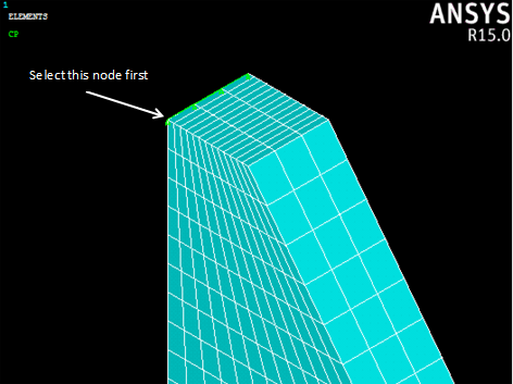
- Select the nodes on the top edge of the pad (x = 0) as shown below, making sure to select the node identified below (z = 0.5) first. Click OK.
- Set the reference number to 100 and the degree-of-freedom label to UY. Click OK to complete the coupling definition.
- Select Preprocessor > Loads > Define Loads > Apply > Structural > Displacement > On Nodes and select the first node from step 2 (x = 0, y = 4.725, z = 0.5).
- Apply a UY value of -20 (mm) and click OK.