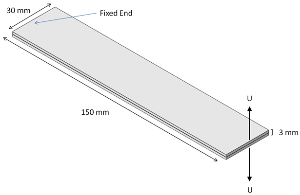
This tutorial provides step-by-step instructions to create and analyze a double cantilever beam (DCB) model that uses the cohesive element functionality of Simulation Composite Analysis. The problem consists of a unidirectional (fiber direction is parallel to long edge of specimen) composite beam that is fixed at one end and is divided by a layer of cohesive elements. Equal displacements applied in opposite directions on the free end of the beam force delamination to initiate at the free end and propagate towards the fixed end in a pure mode I fracture. The DCB dimensions and loading are shown below.
The beam uses C3D8I elements for the plies and COH3D8 elements for the cohesive layer. The recommended value for cohesive element thickness (0.0) will be used.
In this tutorial, step-by-step instructions are provided that cover the creation of the model and interpretation of the results. Elementary modeling details are omitted. It is assumed you have previous experience in the Abaqus/CAE environment. Please refer to the Abaqus documentation before completing this tutorial if you are unfamiliar with Abaqus/CAE.
The Simulation Composite Analysis Cohesive solution is compared to experimental results. Finally, a list of the input file keywords required to use the cohesive functionality is provided if you wish to modify existing input files.
A completed input file (ASCA_Tutorial_4_Abaqus.inp) for this tutorial is available for download here.