To apply a pure mode I loading to the beam, vertical displacements are applied to the free end.
First, an equation constraint is applied to allow for a simple determination of the total reaction force during post-processing.
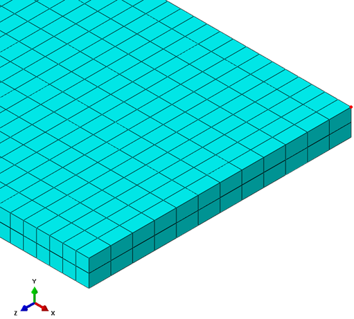
- Create a node set () named Top_Load_Node. Select the node highlighted below.
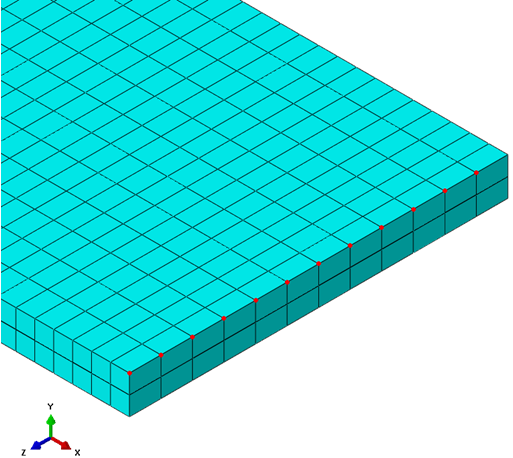
- Create a second set named Top_Tied_Nodes that is comprised of the nodes shown below.
- Switch to the Interaction module.
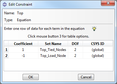
- To constrain the y-direction displacement of the tied nodes to load node, select and select the Equation type. Name the constraint Top. Fill out the Edit Constraint dialog box so that it appears as shown below.
- Repeat steps 1 - 4 to create a constraint for the bottom ply.
- Switch to the Load module.
- Create a Displacement/Rotation type boundary condition called Top. When prompted to select a region, choose the Set option and select the Top_Load_Node set. Enter 10 as the value for U2.
- Create a Displacement/Rotation type boundary condition called Bottom. When prompted to select a region, choose the Set option and select the Bottom_Load_Node set. Enter -10 as the value for U2.