Mesh the part geometry.
Since a layered element is used in this tutorial, a swept mesh is used to define consistent top and bottom element faces. Edge seeding is employed to conserve model size.
- Switch to the Mesh module.
- Click and select all regions of the plate. Change the mesh Technique to Sweep, the Algorithm to Medial axis, and redefine the sweep path so the sweep direction for all regions is in the global positive Z-direction.
- Assign () C3D8R elements to the part.
- Set the global seed size () to 0.03.
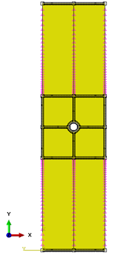
- Bias the red edges () shown below with a single bias ratio of 4 and 30 elements.
- Make sure the bias direction for the red edges is such that the seeds are least dense near the top and bottom of the plate as shown below.
- Seed the edges parallel with the global Z-axis with 1 element so there is a single element through the thickness of the plate.
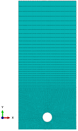
- Mesh the part (). The mesh is shown in the second picture below. There should be a total of 5,468 elements.