Panels on the View tab enable the manipulation of the model and the way the model is presented within the graphics panel.
- Cutting Plane Panel
- Windows Panel
- Navigate Panel
- Viewpoint Panel
Cutting Plane Panel
Inspect the interior of a model using a cutting plane.
- Edit
-
 Open the Cutting Planes dialog to create, edit, and activate cutting planes.
- Move
-
 Open the Move Cutting Plane dialog to inspect different parts of the model's interior.
Windows Panel
Setup the display of multiple windows on the screen.
- User Interface
-
 Activate and deactivate the Navigation Bar and the ViewCube® visibility by checking the appropriate boxes. The Navigation Bar contains the same pan, zoom, and orbit navigation tools found in the Navigate element. The ViewCube® allows you to quickly change the orientation of the model, or return to the default Home view.
Navigate Panel
Use the navigation commands to change the orientation and view of models. You can adjust the display of a model by increasing or decreasing magnification, rotating the model, or using the tools on the Navigation Wheel. You can create a view that defines an area of the model as the Home view. Use the measure tool to measure distances on the model.
- Navigation Wheels
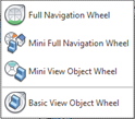
- The drop-down menu lets you select from four different navigation wheels:
| Wheel | Description |
|---|---|
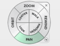
| Full Navigation Wheel
|
Provides access to the general and specialized navigation tools. Optimized for experienced 3D users. |
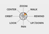
| Mini Full Navigation Wheel
|
Provides access to the general and specialized navigation tools. Optimized for experienced 3D users. |
| Mini View Object Wheel
|
Provides access to the specialized navigation tools used to view model objects with the mouse cursor-size wheel. |
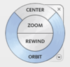
| Basic View Object Wheel
|
Provides rapid switching between 3D navigation tools. Optimized for new 3D users. |

- Navigation Tools
- The Navigate panel also contains the following tools for viewing, manipulating, and measuring the model:
- Select
 Select the model entities you want to work with.
- Pan
 Move the model relative to the center of the model pane. With the Pan tool active, click and hold down the left-hand mouse button while dragging the mouse around the model plane.
- Zoom


 Zoom in and out of the display, zoom to view the entire model, or zoom to a window.
- Orbit
 Change the orientation of a model in a 3-dimensional manner. As you drag the cursor, the model rotates around the pivot point.
- Center
 Center the model and set the center of rotation.
- Measure
 Measure distances on the model.
- Previous View
 Restore the view to the previous position, rotation, and zoom level.
- Next View
 Restore the view to the next position, rotation, and zoom level.
- Home View
 Return the model to the default, centered orientation within the pane.
- View Face
 Position the selected face of the model parallel to the screen.
Viewpoint Panel
Manage and save commonly used views of the display windows.
- Rotation Angle
 Specify the angle of rotation about the X, Y, and Z axes.
- View Name
 Navigate to a saved viewpoint.
- Save
 Save the current view as a viewpoint.
- Delete
 Remove a saved viewpoint from the view list.