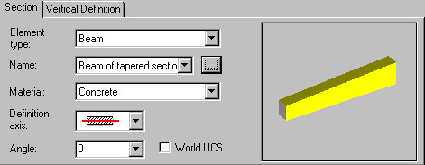
On the Section tab of the Prefabricated element: definition dialog, you can define parameters of the cross-section of a prefabricated element.
Define parameters for each type of cross-section:
- Element type
- beam
- column
- wall
- continuous footing
- slab / raft foundation
- ground beam
- Name - select a solid or click the Browse (...) button to open the dialog from which you can add a new prefabricated element to the list
- Material - select the material from which a prefabricated element is made.
Options that depend on a selected type of a prefabricated element:
- Definition axis - for walls, beams, ground beams, and continuous footings
- Center line

- Upper line

- Lower line

- Center line
When defining a prefabricated element by means of the outer or inner line, you can specify an offset ![]() from the definition line. If the offset equals 0, the definition line coincides with the upper or lower line.
from the definition line. If the offset equals 0, the definition line coincides with the upper or lower line.
- Angle of rotation of the element cross-section - for all element types except walls. Select an available value (0, 45, 90, 135, or 180) or enter a different value. The definition of this angle refers to the current (local) system of coordinates. If you are defining a prefabricated element that lies on an inclined plane, you can select World UCS to define the orientation of the element cross-section with respect to the global coordinate system.
If World UCS is not selected, angle values on the selection list refer to the orientation of an inclined plane. If World UCS option is selected, angle values on the selection list refer to directions of axes of the global coordinate system.
- Handle point - for columns, slabs, and raft foundations:
- Upper Left
- Upper Center
- Upper Right
- Center Left
- Center
- Center Right
- Lower Left
- Lower Center
- Lower Right.