Modification of reinforcement will be illustrated based on changes in parameters of reinforcement generated for a spread footing with the use of the Spread Footing macro. To define the spread footing reinforcement, follow the steps below:
- Click the Spread footing
 icon
icon - In the Spread footing - GEOMETRY dialog specify the following parameters:
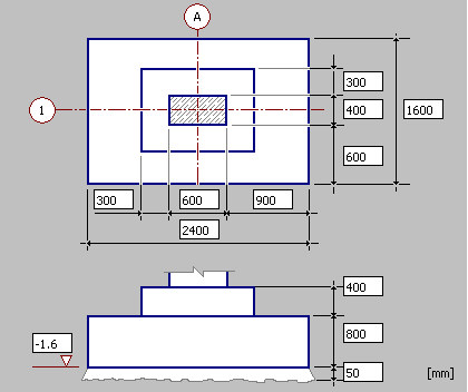
- Element name: spread footing S1
- Number of elements = 1
- Foundation shape - 1 rectangular spread footing
- Column shape - 1 column with rectangular cross-section
- Adopt the dimensions of the column, the spread footing and the column pier as shown in the drawing below
- Click Next; it opens the Spread footing - REINFORCEMENT tab
- Switch off the Top reinforcement of spread footingoption; this type of reinforcement will not be generated in the defined spread footing
- Determine the following parameters of the bottom reinforcement of the spread footing:
- lower layer: f = 12 mm, spacing s = 150 mm
- upper layer: f = 10 mm, spacing s = 250 mm
- steel:R, cover 30 mm
- Determine the following parameters of dowel bars of the column base-column connection:
- reinforcement type: 1
- reinforcement:
o cover = 30 mm,
o number of bars: side A = 3, side B = 2
o f= 12 mm,
o steel: R
- anchorage length: in column = 50*f, in foundation = 50*f
- stirrups:f= 6 mm, spacing s = 180 mm, steel:R
- Click Insert
- Accept the default reinforcement number (given in the command line), click Enter
- Indicate the location of the generated drawing of the spread footing and its reinforcement
- In the case reinforcement parameters or a reinforcement description needs to be modified once the spread footing reinforcement has been defined, the option Modify - Reinforcement or Modify - Reinforcement description should be used.
For example, to modify parameters of the stirrups generated in the spread footing, do as follows:
select the stirrup reinforcement in both sections of the spread footing (see the drawing below)
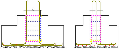
- Right-click Modify option from the context menu
- In the Reinforcement distribution dialog, change the stirrup spacing entering n = 6 (instead of n = 5); the stirrup spacing is adjusted automatically (the change from s=180 mm to s=150mm)
- Click OK; stirrups will be modified in the drawing
- Click the Update tables
 icon
icon - Select the reinforcemet table range: Alland click Enter; the reinforcement table will be modified and it will include new reinforcement parameters.
Similarly, there is a possibility to modify a description of a reinforcement position; after indicating a number of the reinforcement position (label), right-clicking the Modify option from the context menu, the Reinforcement description option appears on the screen. In this dialog, you can select a new reinforcement description style or modify the currently used reinforcement style (after clicking Details).