This option is used to define the geometry for a typical structure used for defining geometry and reinforcement of a continuous footing. Select the option from:
- Menu: Reinforcement > Structure elements - reinforcement > Continuous footing
- Ribbon: ASD - Structure elements > Structure elements - reinforcement > Continuous footing
- Toolbar: Structure elements - reinforcement > Continuous footing
 .
.
The following dialog displays:
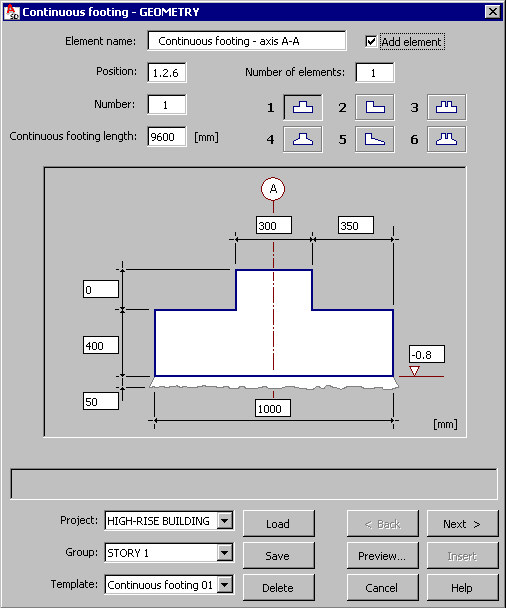
The following information displays in the dialog:
- Name of an RC structure's element (continuous footing)
- Number of position
- Number of defined elements (continuous footings) - this number has an effect on the steel table
- Shape of a continuous footing's cross-section; the following shapes of a continuous footing's cross-section are available (the number is entered into the Number edit field):
 continuous footing with rectangular cross-section
  continuous footing with rectangular cross-section
  continuous footing with rectangular cross-section as a base for two columns
  continuous footing with trapezoidal cross-section
  continuous footing with trapezoidal cross-section
 -
 continuous footing with trapezoidal cross-section as a base for two columns
- Continuous footing length.
Select the Add element option to group the reinforcing bars (or reinforcing wire fabrics) of the continuous footing reinforcement into one element while generating the formwork / reinforcement. The name (an element's name is the name specified in the Element name field) is added on the Model tab of the Object Inspector dialog, and the element (the group of reinforcing bars) is entered into the Element manager dialog.
Once continuous footing geometry is selected, dimension values of the base and the pier of an adjoining column (or columns) should be defined; a schematic drawing of a continuous footing adapts itself to the selected shapes of the continuous footing's cross-section and the column.
In a schematic drawing of a continuous footing another two parameters are also available:
- Description of structural axes (by standard, letter A or letters A and B are entered to denote one direction and digit 1 to denote the second direction - these values are editable)
- Reference level of a continuous footing.
After completing definition of continuous footing dimensions and clicking Next, the Continuous footing - reinforcement dialog displays.