This option is used to define the geometry and reinforcement of a retaining wall. Select the option from:
- Menu: Reinforcement > Structure elements - reinforcement > Retaining wall
- Ribbon: ASD - Structure elements > Structure elements - reinforcement > Retaining wall
- Toolbar: Structure elements - reinforcement > Retaining wall
 .
.
The following dialog displays:
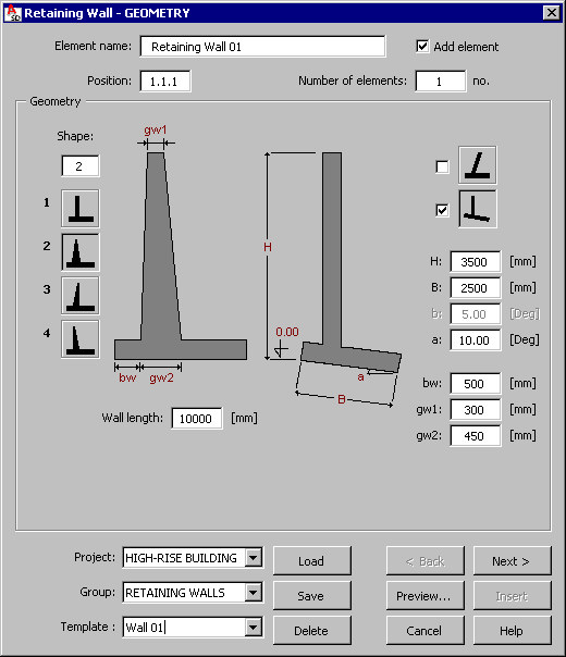
The following information displays in the dialog:
- Name of an RC structure's element (retaining wall)
- Number of a position
- Number of defined elements (retaining walls) - this number has an effect on the steel table.
Select the Add element option to group the reinforcing bars (or reinforcing wire fabrics) of the spread footing reinforcement into an element while generating the formwork / reinforcement of the spread footing. The name specified in the Element name field is added on the Model tab of the Object Inspector dialog. The element (the group of reinforcing bars) displays in the Element manager dialog.
The following selections are available for retaining wall geometry:
- Straight retaining walls (none of the options below is switched on)
- Retaining walls with walls of varying thickness; there are three types of such walls:
 with the front and rear wall surfaces symmetrically inclined
  with the front wall surface inclined and the rear surface vertical
  with the rear wall surface inclined and the front surface vertical.
  retaining walls with the inclined wall
  retaining walls with the inclined footing.
The features of the retaining wall can be combined with each other, i.e. it is possible to define a retaining wall with the wall and footing inclined.
Individual dimensions of a retaining wall are defined in the edit fields located in the right part of the dialog. A number of available edit fields depends on a selected type of a retaining wall.
The lower part of the dialog holds an edit field for defining a length of a retaining wall.
After completing definition of general dimensions of a retaining wall and clicking Next, the Retaining wall - Footing dialog displays.