Use this option to define/modify symbols of axes, levels and sections used in elements of an RC structure. There are several ways to access this option:
- Menu: Reinforcement > Graphic elements > Styles - graphic elements
- Ribbon: ASD - Reinforcement > Settings > Graphic elements styles
- Command line: RBCT_DEF_SYMBOL_STYLE.
After selecting this option, the following dialog displays:
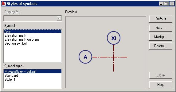
The following types of symbols are used for elements of RC structures (presented in the Symbol field in the dialog):
- Axis symbol
- Elevation mark
- Elevation mark on plans
- Section symbol.
For every symbol type a standard style is defined. After highlighting a symbol type and a symbol style, the current view of the symbol of an axis, level or section is presented in the central part of the dialog (in the Preview field).
The right side of the dialog displays the following buttons (apart from the standard buttons OK, Cancel and Help):
- Default - clicking this button sets a selected style as a default symbol style for an axis, level or section.
- New - clicking this button opens one of the dialog: Axis, Elevation mark, , Elevation marks on plans or Section symbol, where a new style of the selected symbol type are defined (based on the existing style).
- Modify - clicking this button opens one of the following dialogs: Axis, Elevation mark, Elevation marks on plans or Section symbol, where a selected symbol type can be modified.
- Delete - clicking this button deletes a highlighted style from the list of styles available in the Symbol styles field.