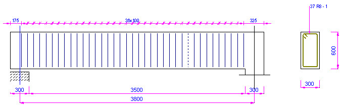
The following drawing illustrates the definition of transversal reinforcement in the cross section of the beam. For definition of the beam contours the Formworks - Beam macro has been used.
To define transversal reinforcement of the RC beam, follow the steps below:
DEFINITION OF THE BEAM FORMWORK
- Run the Formworks - Beam macro by clicking
 icon.
icon. - In the Formworks - Beam dialog specify the following parameters:
- section type: 1 (rectangular)
- beam type: 1 (single-span beam)
- dimensions of the beam cross section: height = 600 mm, width = 300 mm
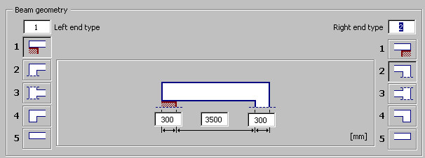
- beam geometry as shown in the drawing below:
-
Click Insert in the Formworks - Beam dialog, and indicate the location of the beam formwork in the drawing.
DEFINITION OF THE BEAM REINFORCEMENT
- Click the Reinforcement - section icon

- In the Reinforcement - cross-section dialog, specify the following parameters:
- type of reinforcing bars: polygon-shaped (closed) stirrup

- bar diameter: 8 mm; cover of reinforcing bars: 30 mm
- steel grade: R
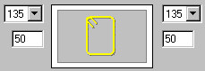
- shape parameters as shown in the drawing below
- type of reinforcing bars: polygon-shaped (closed) stirrup
-
Click
 (Pick point), located on the right side of the dialog.
 -
In the drawing of the beam formwork, indicate a point within the beam cross section and point 1 that determines the position of stirrup hooks.
-
Accept the default reinforcement description proposed in the Reinforcement description dialog by clicking OK.
-
Indicate the position of the reinforcement description by clicking Enter or right-clicking the Enter option from the context menu.
The reinforcement in the beam cross section has been defined. To define the transversal reinforcement distribution along the beam length, follow these steps:
- Click the Reinforcement distribution icon

- Indicate the previously-defined stirrup and click ENTER; the Reinforcement detailing dialog displays. Select the following options:
- Distribution TYPE: linear (press the icon
 )
) - Distribution METHOD: zone (press the icon
 )
) - Viewing DIRECTION: click

- click OK.
- Distribution TYPE: linear (press the icon
-
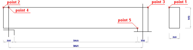
Indicate the start distribution point (point 2 in the drawing presented at the beginning of the example) and the end distribution point (point 3 in the drawing presented at the beginning of the example).
-
Indicate the points of the zone beginning (point 4 in the drawing presented at the beginning of the example) and the zone end (point 5 in the drawing presented at the beginning of the example); click Enter.
-
Accept the default reinforcement distribution by clicking OK.
-
Adopt the following parameters of description of the reinforcement distribution
- Type of reinforcing bar presentation: all

- Position: the Active option switched on
- Type of distribution description:

- Click OK.
- Type of reinforcing bar presentation: all
-
Indicate the location of the reinforcement description in the drawing by clicking Enter, or right-clicking the Enter option from the context menu.
The defined transversal reinforcement with its distribution along the beam length is illustrated below.