To start definition of a workframe, do as follows:
- Click the Workframes option
 .
. - In the Workframe dialog:
- For Name, enter Workframe - 3D Workshop.
- For workframe type, select Box.
- Verify that Surface only, Left diagonal, Right diagonal, and Without description are cleared.
- Select Show axes in drawings.
- On the Size/Division tab, define workframe dimensions with respect to the system axes:
- Width (X): 12000 / 2
- Length (Y): 30000 / 6
- Height (Z): select Non-uniform and click the (...) button.
- In the Line distribution (length) dialog, in the Coordinate column, enter 5000, 7500,9000, and then click OK.
- On the Axis descriptions tab, select descriptions for all the dimensions, and choose the following descriptions for individual workframe axes:
- Width (X): Prefix: wid_, Start value: A, Step: 1, left
- Length (Y): Prefix: len_, Start value: 1, Step: 1, left
- Height (Z): Prefix: pos_, Start value: 0, Step: 1
- Click Create
 (located on the right of the Workframe dialog).
 - Specify the workframe origin and determine the direction of the workframe X axis: direction of the X axis of the global coordinate system (NOTE: the direction of the X axis of the workframe does not need to be compatible with the X axis of the global coordinate system).
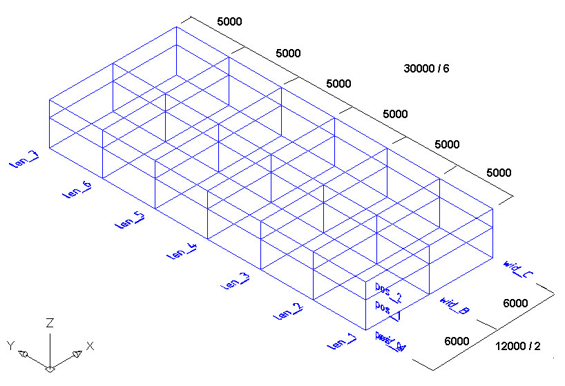
The generated workframe is illustrated in the drawing below.