- On the ribbon, click
 (Connection Vault).
 - Home
 Extended Modeling
(Connection Vault)
Extended Modeling
(Connection Vault) - Extended Modeling Joints
(Connection Vault)
- Home
- From the General bracing category, select
 .
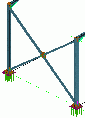
. - Select two beams to connect.
- Enter four points: the start and end points of the ascending and descending diagonal bracing lines. The starting points are at the bottom of the columns. Zoom in to make sure the correct points are selected using the snap NODE.
The bracing is created and can be modified in the dialog box.
![]()